Tony,
You may want to consider using TO3P devices like those used in the kx-Amp OPS for the RE series pass devices. You can mount these on the heat sink - just keep the wires to and from the device to <150 mm and make sure they are twisted together.
OK so I have in my spares MG9411 and MG6331 which are both TO-3P with the right pin-outs:
BCE TO-3P CEO 230V Amps 18A Power Dissipation 300W,
Max °C (Tj) 150C Thermal Resist (Fjc) 0.42 Current Gain (hFE) 70 - 140 VCE (Sat) 2.0V Trans. Freq. (fT) (MHz) 60
Should be OK I assume as replacements for the MJE 15032/15033?
Re the chassis connection
1. all metal parts must be well connected (safety)
2. ensure only one ground point for the entire chassis to prevent earth loops
3. their is an RF screening benefit to be had by having multiple connections between the metal plates as for example when you bolt two pieces of conducting metal together, but you really only need that type of set-up in a heavy RFI environment (many commercial amps have plastic front plates etc. and so break this rule)
I'm getting closer to completing my amp, and I'm running some sims on the PS setup I have, with standard rectifier+caps for the output stage, and separate rectifier + cap multiplier for the front end. All seems fine on normal startup and shutdown, but now I got the idea to try a short grid dropout or 'glitch'. The front end supply drops slower, so the front end can still be 'alive' while the output stage is 'dead', and now I'm trying to simulate a 10V voltage on the front end when power comes back, and LTspice is counting microseconds and not getting anywhere.. This might be a tricky situation where the bias voltage is still present while the power comes on to the output stage?
I'm thinking of some way to prevent this, and my first thought was to put some diodes and resistors linking the rails, so the front end rails can only be abt one diode drop higher than the output rails (in normal operation front end rails will be slightly lower than the output rails due to voltage drop in the cap multiplier)
I'm thinking this should suck out the energy from the cap multiplier as soon as the output rails go down. The resistor would be just to limit the current drawn from the cap multiplier, but might not be needed since I have some PTC's on the cap multiplier output.
Does somebody have some insight / suggestions on this?
Last edited:
The above sim never finished, so I canceled it.
Seems like a diode an 10 Ohm resistor between the rails would do it. Cap multiplier current peaks at abt 0,2A at shutdown, and gives a reasonably quick discharge of the front end supply.
Do any of you see any downsides to this approach?
Seems like a diode an 10 Ohm resistor between the rails would do it. Cap multiplier current peaks at abt 0,2A at shutdown, and gives a reasonably quick discharge of the front end supply.
Do any of you see any downsides to this approach?
Rallyfinnen ,
Sounds like a simulation convergence issue you have and nothing to do with the circuit itself.
There are diodes around the cap multiplier that are designed to rapidly discharge the multiplier cap. In addition, since the load is high (2.4 Amps for a full class A implementation) the discharge time should be quite quick. Estimate it from it=CV so t ~ (100mf*25)/2.5 ~ 1 second. It will in practice be longer than this as once the front end voltage starts to drop, the OPS current also drops, so expect 5 secs or so practically.
With a typical brown out, you get a mains voltage dip for a few cycles. The kx-PSU (straight or cap multiplier version) should handle this ok since the filter caps are big (47 mfd per rail).
Last edited:
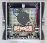
xK Amplifier PSU has now in chassis as per attached photo.
25-0-25V 500W transformer feeds 2 sets of secondary fuses, the outputs of which go to 2 Ripple eaters.
The Ripple eaters are then separately connected to 2 banks of external caps (3 by 4,700 uF 63V caps per rail). Note the output transistors of the REs have been changed from MJE to 2SA1295/2SC3264 (because I had excess stock of them) higher current/power handling transistors.
Now comes the power and ZN connections to the xK amps themselves.
Option 1:
Run twisted wires from the end of the cap banks to the power in of the xK amps. Problem arises on how to run the 'loan' ZN wire from the Ripple eaters to the xK amps.
Option 2:
Run the twisted power cables, along with the ZN wire, from the Ripple Eater's terminal themselves.
I would imagine that taking the PSU supply from the ends of the cap banks (Option 1) would be more desirable but then the ZN wire would not be wound - or just wound with the PSU wires for a short distance prior to the attachment to the amp power inputs.
Any thoughts/recommendations?
BTW,:
1) The xK amps are set to run under Class AAB mode at ±33V
2) The xK amps have been added to only 1 of the 2 available heatsinks provided per side such that the 'spare' heatsinks can be used for 2 different amp modules at a latter date. (Each heatsink is rated at 0.38 °C/W)
Attachments
Rallyfinnen ,
Sounds like a simulation convergence issue you have and nothing to do with the circuit itself.
There are diodes around the cap multiplier that are designed to rapidly discharge the multiplier cap. In addition, since the load is high (2.4 Amps for a full class A implementation) the discharge time should be quite quick. Estimate it from it=CV so t ~ (100mf*25)/2.5 ~ 1 second. It will in practice be longer than this as once the front end voltage starts to drop, the OPS current also drops, so expect 5 secs or so practically.
With a typical brown out, you get a mains voltage dip for a few cycles. The kx-PSU (straight or cap multiplier version) should handle this ok since the filter caps are big (47 mfd per rail).
Not sure if you read this: the PS setup I have, with standard rectifier+caps for the output stage, and separate rectifier + cap multiplier for the front end
The output supply dies quickly because of the high current, but the front end keeps running for a couple of seconds after that. So if power comes back in a second the output supply will be close to 0, and the front end alive and biased. 1-3 sec is actually the standard here for the protection setting on the grid. If there is a storm and some tree haw fallen on a high voltage line, the system will retry after 1sec or so, if the problem is still there, it will cut again, and retry for another 1-2 times, after that there is usually a longer blackout where they have to go and fix the problem. Sometimes it's back after one or two tries.
Anyway, what I did was to add the resistors and diodes to pull down the front end supply with the output supply. Better safe than sorry as the saying goes.
Now I'm only wondering if I should remove or keep the RC I added as a first stability fix before I start to assemble the amp. I cant get my stability sims running, I get error messages with whatever stability sim I try to run. Posted a question about it in Sandro's thread a while ago. I would like to compare the sim results before I decide..
@polsol
Looks very neat!
Did you not move the output zobel to the amp boards? If you do that there is no complications, and you can go for option 1.
It looks like you have the ground connected to the center point of the big cap bank? Usual recommendation is to put a 'tab' to the side where you connect it to avoid the pulse currents from the rectifier pulses passing between the caps, but since you have the ripple eaters before, there should be no serious pulses, so I guess it's ok in this case.
I have done some tests with this PS setup now, and I see a brief oscillation at startup, when the front end voltage comes up (and the output stage has full voltage). It's abt 200mV p-p with the RC over R4&R5 in place, and abt double amplitude without it with some 'crossover distortion' with the higher amplitude oscillation. It seems to be the same ~16MHz frequency as before, and it lasts for less than a second.
I'm thinking I will leave it like that, but leave the RC in place. Or should I worry about the brief startup oscillation?
Square wave looks clean even without the RC though. Seems there are no tendencies to oscillate once it's up and running.
I'm thinking I will leave it like that, but leave the RC in place. Or should I worry about the brief startup oscillation?
Square wave looks clean even without the RC though. Seems there are no tendencies to oscillate once it's up and running.
Not sure if you read this: the PS setup I have, with standard rectifier+caps for the output stage, and separate rectifier + cap multiplier for the front end
@polsol
Looks very neat!
Did you not move the output zobel to the amp boards? If you do that there is no complications, and you can go for option 1.
It looks like you have the ground connected to the center point of the big cap bank? Usual recommendation is to put a 'tab' to the side where you connect it to avoid the pulse currents from the rectifier pulses passing between the caps, but since you have the ripple eaters before, there should be no serious pulses, so I guess it's ok in this case.
Thanks Rally.
Nope, the Zobel is still on the ripple Eaters. Trying to keep it neat.
The 0V line (orange wires) from the 'fuse box' goe to the '0V IN' on the RE (separate lines from the fuses to each) the '0V' out (white wire) of each RE is taken to the central point of the large cap bank 'busbar'.
In other words the '0V' is a straight line connection from the fuses, via the REs) to the central cap bank position.
Similarly the AC lines (Yellow and Black) from each fuse box go to the 'AC IN' on the REs and the 'DC Out' lines from each RE to the centre on either side of the cap bank (Red and Black wires).
The ground/chassis earth is connected to the chassis below the mains input RFI and then fed under the inner chassis panel and connects to one RE 'Earth Point' only to prevent any possible ground loops.
In other words the '0V' line of the cap bank is raised over the mains earth by the second bridge rectifier into the RE above the chassis/ground - as per the original design
As you mentioned, I was somewhat worried about the cap bank ripple current if I connected the '0V' line from this central point to the xK amps directly. I'm not sure one could call it a 'star ground' where it's placed.
Cheers
That was my point about the central point of the cap bank, the general recommendation is to have a T-shape and connect the 0V on the end of the T to avoid the ripple currents going between the caps. But, in your case ripple currents should be almost 0 since you have the ripple eater before the cap bank.
I have done some tests with this PS setup now, and I see a brief oscillation at startup, when the front end voltage comes up (and the output stage has full voltage). It's abt 200mV p-p with the RC over R4&R5 in place, and abt double amplitude without it with some 'crossover distortion' with the higher amplitude oscillation. It seems to be the same ~16MHz frequency as before, and it lasts for less than a second.
I'm thinking I will leave it like that, but leave the RC in place. Or should I worry about the brief startup oscillation?
Square wave looks clean even without the RC though. Seems there are no tendencies to oscillate once it's up and running.
I have the same brief oscillation during startup. I have found out that the oscillation is much shorter, when I disconnect one channel from DAC (left or right challel - does not matter). So I suspect that ground loop between DAC ground and power amp ground is playing some role. I use one transformer and one RE now. I plan to upgrade with two transformers and REs later.
As far as the problem of drop out of electric power for a second or so, I use soft start that prevent from switching on after drop out. I hope this could help.
"Option 2:
Run the twisted power cables, along with the ZN wire, from the Ripple Eater's terminal themselves.
I would imagine that taking the PSU supply from the ends of the cap banks (Option 1) would be more desirable but then the ZN wire would not be wound - or just wound with the PSU wires for a short distance prior to the attachment to the amp power inputs."
_______________________________________________________________
Just twist the ZN with the +- and 0V. Then continue the ZN over the cap bank 0V and on to the PSU and terminate it on the ZN Tab connector. By keeping the ZN wire close to the cap bank 0V and twisting it with the +- and 0V from the amp module to the cap bank, you are minimizing the loop area. It should be ok. If not, you may have to move the Zobel onto the amp board. But I'd try it like I am suggesting.
You can easily check that everything is ok by looking at the output with a scope and feeding the amp with a c. 1 kHz sine wave so that its swinging about 70-80% of the rails. If its unstable, you will see it break into oscillation near the peaks. The other thing to do if that is ok is to drive the amp so it clips and check that it exits clipping cleanly without ringing. Finally, inject a square wave on the input so that you get about 2Vpk-pk on the output. The square wave should be clean without overshoot ringing, remembering that this is a TPC completed amp, so you will get overshoot but its critically damped so there is no ringing.
These tests are not exhaustive, but will expose loop gross compensation problems and OPS/VAS parasitic oscillation issues.
Beautiful construction job BTW Tony!
Re start up oscillation, you often get this sort of thing when amps power up so I would not get too worried about it if its below a few hundred mV. I personally have not experienced any of this on either the sx or kx Amps so it may be specific to your installation.
@Rallyfinnen
"Now I'm only wondering if I should remove or keep the RC I added as a first stability fix before I start to assemble the amp. I cant get my stability sims running, I get error messages with whatever stability sim I try to run. Posted a question about it in Sandro's thread a while ago. I would like to compare the sim results before I decide."
______________________________________________________________
You will need to either leave you RC networks in, or reduce R4 and R5 to 1k. Without either one of these two fixes, there is a chance you will get into trouble. IIUC, Tony does not have anymore problems (he has also added a 1k resistor in series with each collector of Q1 and Q2 - see the latest kx-Amplifier build doc for a photograph on how he did it).
re the PSU power up/down issue - ok - got it now, thanks
(NB - I did try to contact Sandro when this issues first raided his head to get another pair of eyes on it, but no reply - I guess he is busy - but we have in any event solved it now)
Last edited:
Yes, I have all the options installed (as per schematic I posted earlier in the thread) 🙂
I kept the RC's too, since the startup oscillation was milder with them in place.
The amp is assembled and I did some listening yesterday. Strangely I have a little bit more hum/noise now than I had in the 'prototype setup'. Audible with ear to the speaker. I think I have to replace the input cables (internal amp wiring), because I just used what I had, and from memory they were left over because of some issues.
Too bad Sandro did not have time to take a look, I think he could have contributed with some insights and maybe things to experiment with.
"Option 2:
Run the twisted power cables, along with the ZN wire, from the Ripple Eater's terminal themselves.
I would imagine that taking the PSU supply from the ends of the cap banks (Option 1) would be more desirable but then the ZN wire would not be wound - or just wound with the PSU wires for a short distance prior to the attachment to the amp power inputs."
_______________________________________________________________
Just twist the ZN with the +- and 0V. Then continue the ZN over the cap bank 0V and on to the PSU and terminate it on the ZN Tab connector. By keeping the ZN wire close to the cap bank 0V and twisting it with the +- and 0V from the amp module to the cap bank, you are minimizing the loop area. It should be ok. If not, you may have to move the Zobel onto the amp board. But I'd try it like I am suggesting.
You can easily check that everything is ok by looking at the output with a scope and feeding the amp with a c. 1 kHz sine wave so that its swinging about 70-80% of the rails. If its unstable, you will see it break into oscillation near the peaks. The other thing to do if that is ok is to drive the amp so it clips and check that it exits clipping cleanly without ringing. Finally, inject a square wave on the input so that you get about 2Vpk-pk on the output. The square wave should be clean without overshoot ringing, remembering that this is a TPC completed amp, so you will get overshoot but its critically damped so there is no ringing.
These tests are not exhaustive, but will expose loop gross compensation problems and OPS/VAS parasitic oscillation issues.
Beautiful construction job BTW Tony!
Thanks Bonsai.
Thus far I have the 'construction' with the A/C fuses feeding the bridge rectifiers on the REs and then on to the Cap Bank as per previous picture.
Amp A
Connected to the end of the Cap bank power with straight wires, ZN connected to the RE. Input shorted.
Amp B
Connected directly to the RE (power and ZN) using tightly twisted wires. Input shorted.
1) Amp B connected to Dummy load (Amp A no load): 18 to 19 MHz oscillation at 37 mV RMS
Disconnect Amp A from Cap Bank
1) Amp B connected to RE and dummy load: Ringing oscillation 667 Khz, 83 mV RMS
2) Amp B connected to RE and dummy load, RE disconnected from cap bank: Ringing oscillation 625 KHz, 60 mV RMS.
3) As per (2) but no dummy load: Ringing oscillation 667 KHz, 80 mV RMS
Amp B connected to Cap Bank (Cap bank 'fed' by RE), Zn connected (single wire) to RE
1) With Dummy load: Ringing Oscillation at 694 KHz, 80 mV RMS
2) No dummy load: Ringing Oscillation at 694 KHz, 107 mV RMS
Summary:
When Amp B is connected with twisted wire (including Zn) via the RE or 'single wires' via the Cap Bank I get a ringing oscillation of around 80 mV RMS or so at 650 - 700 KHz with or without a dummy load.
Strange case is that if I connected Amp A to the cap bank (too lazy to twist wires at this point) then I get the 18 MHz parasitic back again.
BTW, both amps were tested using the 'Cap Bank' (no RE in parallel) on my Lab bench and were OK after the mods.
Only thing I can think of at this stage is the wiring to the RE which I'll investigate further. What I may do is separate the RE and Cap Bank and run them individually and see what happens. I suspect the long AC lines from the Transformer to the RE might be the culprit. Although it might possibly be the bridge rectifiers I used on the RE (I picked up locally - DC Components GBK25M from memory)?
Anyway, this is just a short note to let you know what is happening for information purposes.
As a general note to builders, be careful putting fuses before capacitors on tne secondary side of a transformer where there are large charging currents. After a while the fuses could fail.
On the primary side, the peak charging currents reflected back from the secondary are of course reduced by the transformer turns ratio factor.
On the primary side, the peak charging currents reflected back from the secondary are of course reduced by the transformer turns ratio factor.
Not sure if you are referring to me?Can you post a picture?
Unfortunately I've already 'pulled the wires' whilst experimenting.
Otherwise it's the same as post 667 picture with straight wires from the cap bank on the left side plus a single wire to the RE Zn ('Amp A') and twisted wires (including the Zn connection) from the right RE to the 'Amp B' board as per 'standard'.
Cheers
- Home
- Amplifiers
- Solid State
- Hifisonix kx-Amplifier