Go for more ampere instead of voltage:What very good SMPS can be taken into account to power the T4?
Cosel power supply PBA1000F-48 DC48V / 22A free ship | eBay
Thank you for your answer.
I got a second question: I found a good high end torroid with 2x40V 600VA
Highend Audio-RKT V-RKT-MS-SW vergossen - hifituning24.de
The 2x40V are load-voltage. The off-load-voltage might be higher, up to 2x45V, I guess. You mention that 2x40V is ok for the T4. Is this 2x40V what is printed on the torroid or is it real maximum voltage?
...
Thank you very much!
IMO, you may be overboard on DC voltage once rectified. I used a 500 VA 2 x 35V and with USA voltage, once rectified I get 49.9 VDC.
Also, with 600 VA, you may need to use some kind of inrush current limiter like an NTC Thermistor so that you do not stress the power supply components at power on.
Make sure the rectifier is rated for the amperage load of the power supply or it will be first to go at power on.
Just some thoughts, but I think this is worth the effort over a simple SMPS plug-in type...no pain, no gain.
Last edited:
Whaleman, thank you for your thoughts.
This was just a test with no connected board, I guess? What have you invented with your board in the last days? You at first used a small 2x30V transformer and were very happy with it, I think.
Could you please measure the voltages at certain points of the soldering side of the rectifier and the caps?
The T4 is specified for 2x38V to 2x40V AC. This is perfect for a good 2x35V toroid. I explained this some posts ago.
Hifimediy has agreed to this.
The rectification is no problem. It is done on the board. The rectifier might get overloaded only if added some more external caps parallel to the existing caps by short wire.
In a few days I will receive the board. I will follow the strip conductors to check how to desolder the rectifier to replace it with an external type of maximum power (100A, no problem with that!). I hope that this will be possible (multlayer).
@hifimediy: could you give us some more hints about current supply?
A circuit diagram of the onboard power supply and rectification including the caps would be very appreciated.
I think you will not be in danger to tell secrets about this part of the board - the power supply is not that complicated to the competition.
Thank you!
I used a 500 VA 2 x 35V and with USA voltage, once rectified I get 49.9 VDC.
This was just a test with no connected board, I guess? What have you invented with your board in the last days? You at first used a small 2x30V transformer and were very happy with it, I think.
Could you please measure the voltages at certain points of the soldering side of the rectifier and the caps?
The T4 is specified for 2x38V to 2x40V AC. This is perfect for a good 2x35V toroid. I explained this some posts ago.
Hifimediy has agreed to this.
The rectification is no problem. It is done on the board. The rectifier might get overloaded only if added some more external caps parallel to the existing caps by short wire.
In a few days I will receive the board. I will follow the strip conductors to check how to desolder the rectifier to replace it with an external type of maximum power (100A, no problem with that!). I hope that this will be possible (multlayer).
@hifimediy: could you give us some more hints about current supply?
A circuit diagram of the onboard power supply and rectification including the caps would be very appreciated.
I think you will not be in danger to tell secrets about this part of the board - the power supply is not that complicated to the competition.
Thank you!
Last edited:
40 volts AC will rectify around 57 DC, you may too close or over I think. I use my own rectifier and feed the board DC.
With everything connected, I measure 49.9 VDC at the power connector with a 35-0-35 AC toroidal. I add 75,000 uF of capacitance outside the board, so my power on current rush is substancial and I have to use a bigger rectifier.
Double check your voltage before you buy the toroidal, those aren't cheap.
@ whaleman: Thank you for your reply.
You are right. One may not use 2x40V toroids. Maximum 2x35V are allowed.
Sorry I did not understand everything you pointed out.
You have a 2x35V toroid. From the toroid you go into a rectifier.
How do you do it? Toroid has 2 outputs, each with 35V. Do you use both?
Do you have 2 rectifiers? Each rectifier with caps and 49,9V DC?
Or do you parallel circuit both toroid outputs for double power at 35V?
Or do you use only one toroid output?
And how do you connect the power to the board? For AC power the board has 3 connectors. The board is specified for AC 30V-40V - 0 - 30V-40V. This is up to 80V AC. DC only 54V are allowed. Feeding DC, you loose a lot of voltage. Do you feed 1x49.9V DC at the mid and the left connector?
Please explain why. On your photos you feed AC. Why have you changed this?
Last not least, if one wants to feed DC, he needs not a toroid with 2x35V. 2x18V would be enough for 36V in series connection. Is that right?
@ hifimediy:
I do not understand one fact:
Why are 80V AC allowed but only 54V DC? The about 110V DC out of the 80V AC will face the 54V DC input. This means, that AC voltage is double than DC. What trick is used?
Sorry, I do not understand this and I will not go for a PS until I have understood this.
Last edited:
Here we find a thread in Italien with many photos:
Hifimediy T4
or translated
Google Übersetzer
We can follow the ebay link where he bought his toroid
Trasformatore Toroidale 500VA 230V out 36-18-0-18-36 | eBay
and find out that the toroid has following voltages
36-0-36 red black red
18 - 0 - 18 yellow black yellow.
It has 500VA.
Fuse and power switch seems to be integrated into the device socket.
Cables connected to the T4 are red black red. The T4 is powerd with
2x36V AC 500VA.
This helps me a lot but does not answer my questions about the AC-DC voltage difference.
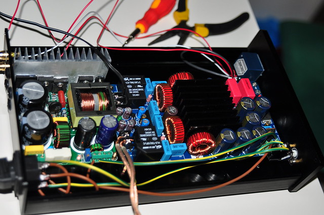
The 3-leg component near the connectors seems to be a MUR3020PT which is some kind of switching power rectifier with 200V and 30A. This should be enough and there is no reason to remove it after adding some additional caps which are conected to the existing caps of the board.
Hifimediy T4
or translated
Google Übersetzer
We can follow the ebay link where he bought his toroid
Trasformatore Toroidale 500VA 230V out 36-18-0-18-36 | eBay
and find out that the toroid has following voltages
36-0-36 red black red
18 - 0 - 18 yellow black yellow.
It has 500VA.
Fuse and power switch seems to be integrated into the device socket.
Cables connected to the T4 are red black red. The T4 is powerd with
2x36V AC 500VA.
This helps me a lot but does not answer my questions about the AC-DC voltage difference.
The 3-leg component near the connectors seems to be a MUR3020PT which is some kind of switching power rectifier with 200V and 30A. This should be enough and there is no reason to remove it after adding some additional caps which are conected to the existing caps of the board.
Last edited:
Sorry for the double post. I do not find no edit-button.
At last, I have solved the problem.
The T4 uses a MUR3020PT which is a push pull rectifier which needs a transformer with center tap.
A push pull rectifier will output half of the input voltage x1.4 and double the current of the transformer.
A Graetz rectifier will output the input voltage x1.4 and the current of the transformer.
If you connect a 2x38V AC 2x5A toroid to the T4 the MUR3020PT will output 1x53.2VDC at 10A.
This ist the maximum DC input voltage for the unit as described on the hifimediy homepage. AC or DC feeded into the T4, the result after the MUR will be the same.
You see, there are three ways to connect the toroid to the T4:
-Directly feed the T4 with AC. It is difficult to add additional caps.
-Parallel circuit toroid outputs and feed a Graetz rectifier with some caps behind. Feed the DC into the T4.
-Use the toroid with a push pull rectifier, add some caps and feed the DC into the T4.
As the push pull rectifier you could use a MUR6020PT to deal with the high current of the caps. The MUR does hardly heat up so this might be the best of the 3 solutions.
Thank you.
What do you think about? Can you compare it with some other amp?Finally got my T4 working after waiting for the SMPS module for three weeks
the only other amp that I have is an Onkyo AVR.
with T4, I'm hearing a more detailed sound (apologies as I do not know much of audio jargons).
with T4, I'm hearing a more detailed sound (apologies as I do not know much of audio jargons).
Finally got my T4 working after waiting for the SMPS module for three weeks
I found the parts placed too close together. But on the other hand:
it should be the smallest and lightest 2 x 180 W (8 Ohms) amp of the world .... A small giant killer ?😀
yeah, i agree that its kinda cramped inside the case. my mistake for buying the case too early. good thing every thing fits inside. will be pairing them with markaudio Alpair 10.2 bookshelfs soon. good thing I wandered into the class D subforums 🙂
40 volts AC will rectify around 57 DC, you may too close or over I think. I use my own rectifier and feed the board DC.
With everything connected, I measure 49.9 VDC at the power connector with a 35-0-35 AC toroidal. I add 75,000 uF of capacitance outside the board, so my power on current rush is substancial and I have to use a bigger rectifier.
Double check your voltage before you buy the toroidal, those aren't cheap.
Though I know you pointed out this issue also in the other Hifimediy thread I am digging this Thread up again. It really belongs more into here.
I am using a 450 VA torroidal and the set up on the T4 board. First listenning impressions were O.K. but I got the strong impression that there is quality space above. So can you state the rectifier type you used ? Isn't it also better to split the total capacitance into smaller ones - i.e. 20 x 3500 uF ?? If I am not wrong you did not remove the standard T4 rectifier, or did you ?
The rectifier bridge I used is this one: 400V 25A Bridge Rectifier
I have done the power capacitors both ways, spread out and a single large one or two. I like the large one because it takes a while to drain and it is like running the amp on a battery. The T4 runs for 30 seconds after turn off with no power without any degradation to sound quality, which means that it is very well fed. I use bypasses on it. Also, I left the rectifier on board, I did not modify the T4 board at all. I think the unit is optimized and I don't see how it could sound any better, it is quite impressive. BTW, I used a 500 VA toroidal and an NTC thermistor as an inrush current limiter.
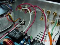
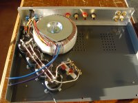
Here are both, one with a 75,000 uF capacitor, plus what is on the T4 and the early stages setup for the T1 with 4 x 12,000 uF capacitors in series and a intermodulation distortion reducing circuit I picked up from TNT audio. The thermistor for the T4 was added after these pictures.
Attachments
Last edited:
Whaleman,
thanks much for the clearing statements. I think I will go up to 20.000 uF.
Maybe I check also up the difference between 1 x 20.000 and 10 x 2.000 version from same cap model.
thanks much for the clearing statements. I think I will go up to 20.000 uF.
Maybe I check also up the difference between 1 x 20.000 and 10 x 2.000 version from same cap model.
Please can anyone help with this issue ...
I am a bit confused now.
I cleared the AC input with the seller regarding this assembled powersupply board for T4:
Power Supply Module Board, for HP Audio Amplifiers DIY. | eBay
And now a technician told me that the DC outputs of this supply board is not matching with the T4 because T4 accepts only a positive and GND voltage type and not negative and positive. Is that right ? Is this board useless with T4 ?
That is a very nice board, and yes it is setup for center tap (GND) but it is still very much usable for the T4. You just do not use the center tap and hook up neg as DC ground. Did you already buy it?
Here is where I think this power board would not reach its potential--some with engineering degree can confirm this--but when you use it as above without the center tap, you will waste 1/2 the capacitance? Meaning that those 6,800 uF caps will appear as 3,400 uF caps when hooked up in series with the center tap not used? They will still work, but only 1/2 their potential.
Make sure not to exceed approx. 50 VDC output, so AC input should be less than 50 / 1.44 or about 35 AC. I think the T4 can go to 54 VDC, but you want some safety buffer.
All this from memory, please confirm.
Last edited:
Indeed, it is not a lucky feeling to paid for things you finally cannot use. So I am going to look elsewhere or build one myself.They will still work, but only 1/2 their potential.
I am measuring 2 x 37 VAC input on T4 and it is working for burning purpose 24 hrs since 1 week. The sound is regarding the 6 standard small caps on board very acceptable. But there is still quality space to the top. You can listen it out ...Make sure not to exceed approx. 50 VDC output, so AC input should be less than 50 / 1.44 or about 35 AC. I think the T4 can go to 54 VDC, but you want some safety buffer.
All this from memory, please confirm.
Thanks much for your solid help.
I am a bit confused now.
I cleared the AC input with the seller regarding this assembled powersupply board for T4:
Power Supply Module Board, for HP Audio Amplifiers DIY. | eBay
And now a technician told me that the DC outputs of this supply board is not matching with the T4 because T4 accepts only a positive and GND voltage type and not negative and positive. Is that right ? Is this board useless with T4 ?
Did you try connecting both positive and negative DC and the GND in the middle? It should work.
- Status
- Not open for further replies.
- Home
- Amplifiers
- Class D
- Hifimediy T4 board