I'm certain that your BD player etc can compensate...
Thanks, this make sense. I have to check it for this option in the TV as well.
And it depends on the filter. You can offcource use IIR filters for low latency TV.
I mean:
High latency FIR filters for HiFi and Blueray etc and
Low latency IIR or FIR filters for live TV.
The speakers will then have two sets of filters.
The high latency filters may be a little better, but the low latency filters may be good enough for TV.
I use MiniDSP IIR filters for TV speakers and it is "in sync" when using sound out (TV - toslink - DAC - analog - MiniDSP - analog - AMP) from TV.
Last edited:
It seem pretty apparent that some are confusing the speed needed to process a digital signal with the requirements for audio playback. DSP processing of a multiple FIR filter can require much higher processing speed than just playing back an audio signal from a CDP or BlueRay player with an analog xo. You do have to consider where in the audio chain you are to determine whether you can get away with 24/96 or need much higher speeds.
Quick question here: What type (brand) of display do you use. It seems very clear and crisp on the picture.
BTW, super clean job.
It's a QVGA (320x240) resolution full color 3.2inch LCD display 😉
cheers
My MiniDSP ADAU1701 is 50 MHz and this is 10 times that + enhanced arcitecture.
So at least 10 times the prosessing can be done in the same timeframe (same latency).
But, the FIR length latency is decided by the samplerate with classic FIR filters.
I don't know if there are some new smart prosessing strategies to overcome FIRlength latency for prosessing latency lower than FIR length latency.
I think I have read about it somewhere for VSTs, but maybe it is marketing hype or I did not understand?
Still don't understand, but I see that long FIR filters with low latency can be done:
Example GPU prosessing of audio (se paper for proper formating):
From http://dafx10.iem.at/papers/WefersBerg_DAFx10_P76.pdf Chapter 5.5. Dynamic filtering
Block Filter Maximum Average GPU
length length number of stream processing load
[samples] channels runtime [ms] [%]
128 1,0 s 118 1,77 ms 41%
128 2,0 s 58 1,47 ms 40%
128 5,0 s 7 2,06 ms 68%
Table 3: Static filtering performance achieved on the test system.
Here, filters are time-invariant and not changed during runtime. A
sampling rate of 44.1 kHz was used, resulting in filters of 44.100,
88.200 and 220.500 coefficients. All values have been measured
under stable operation.
Example GPU prosessing of audio (se paper for proper formating):
From http://dafx10.iem.at/papers/WefersBerg_DAFx10_P76.pdf Chapter 5.5. Dynamic filtering
Block Filter Maximum Average GPU
length length number of stream processing load
[samples]
128 1,0 s 118 1,77 ms 41%
128 2,0 s 58 1,47 ms 40%
128 5,0 s 7 2,06 ms 68%
Table 3: Static filtering performance achieved on the test system.
Here, filters are time-invariant and not changed during runtime. A
sampling rate of 44.1 kHz was used, resulting in filters of 44.100,
88.200 and 220.500 coefficients. All values have been measured
under stable operation.
Last edited:
It's at the output of the DAC. If the signal is clipped before the SRC then it will be clipped after the SRC because the S/PDIF cannot handle anything above FS. I noticed that if I force the output of the sound-blaster to re-sample at 96kHz then neither signal is clipped.
cheers
Strange, didn't think the resampled signal could be sent over S/PDIF without attunating so that all samples are at or under 0dbFS.
Last edited:
Strange, didn't think the resampled signal could be sent over S/PDIF without attunating so that all samples are at or under 0dbFS.
When I scale down the inputs to the SRC by half the clipping goes away as you would expect.
But to restore the level I then scale up the output of the SRC and then I get the same clipping phenomena in the DSP but the right channel is ok with correct amplitude as it is not been driven into overload.
But when I inject the 44.1K signal directly into the DAC there is no clipping because it does not upsample to another sampling rate. Upsampling from 44.1K to 192K is producing samples that overdrive the SRC or proceeding signal chain. It's purely a mathematical phenomena and the solution is to pre-attenuate the signal to the SRC to account for the worst case signal.
regards
Last edited:
Just what I was looking for! Hope this can be done in the DSP/box so I don't have to do it at the source.
Ref post #395
Thank you for looking into this!
It really has an impact of how overdriven digital signals (commonly found in modern pop and rock) sound. I think it is somewhat similar in sound to difference between an overdriven tube and transistor.
Worst case is SR/2 sine. Think -3dB attunation will do the trick to avoid "transistor like" clipping from FS/4 and lower. SR/2 can be +8.3dBFS at 22.5 phaseshift. I think SR/2 is to high frequency to be a problem.
Regards Torgeir
Last edited:
Just what I was looking for! Hope this can be done in the DSP/box so I don't have to do it at the source.
Ref post #395
Thank you for looking into this!
It really has an impact of how overdriven digital signals (commonly found in modern pop and rock) sound. I think it is somewhat similar in sound to difference between an overdriven tube and transistor.
Worst case is SR/2 sine. Think -3dB attunation will do the trick to avoid "transistor like" clipping from FS/4 and lower. SR/2 can be +8.3dBFS at 22.5 phaseshift. I think SR/2 is to high frequency to be a problem.
Regards Torgeir
According to that AES article you provided the link for a 6dB buffer will allow for a worst case scenario so 6dB it is 😉 It's funny but what do DAC's that don't have any DSP to attenuate the signal into the SRC do to avoid this issue ?
Guess they don't avoid the issue.....
Might be wrong, but i think SACD has -6dB volum to avoid the problem.
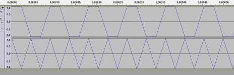
Just for fun if someone like to try, a file is enclosed with right channel
Dim Freq As Double = 22050
Dim SF As Double = 44100
Dim Phase As Double = 22.5
Dim Ampl As Double = 2.6 , 8.3dBFS
and left channel:
'Dim Freq As Double = 11025
'Dim SF As Double = 44100
'Dim Phase As Double = 45
'Dim Ampl As Double = 1.41, 3.0 dBFS
Mind the volume so that no tweeters are harmed!!!
Might be wrong, but i think SACD has -6dB volum to avoid the problem.
Just for fun if someone like to try, a file is enclosed with right channel
Dim Freq As Double = 22050
Dim SF As Double = 44100
Dim Phase As Double = 22.5
Dim Ampl As Double = 2.6 , 8.3dBFS
and left channel:
'Dim Freq As Double = 11025
'Dim SF As Double = 44100
'Dim Phase As Double = 45
'Dim Ampl As Double = 1.41, 3.0 dBFS
Mind the volume so that no tweeters are harmed!!!
Attachments
Guess they don't avoid the issue.....
Might be wrong, but i think SACD has -6dB volum to avoid the problem.
Just for fun if someone like to try, a file is enclosed with right channel
Dim Freq As Double = 22050
Dim SF As Double = 44100
Dim Phase As Double = 22.5
Dim Ampl As Double = 2.6 , 8.3dBFS
and left channel:
'Dim Freq As Double = 11025
'Dim SF As Double = 44100
'Dim Phase As Double = 45
'Dim Ampl As Double = 1.41, 3.0 dBFS
Mind the volume so that no tweeters are harmed!!!
Without the 6dB attenuation the left channel clips and the right channel is OK. With 6dB attenuation there is no clipping 😉
I am making this option switchable from a menu so you can easily do a comparison between the two settings although the 6dB attenuation reduces the volume 😉
cheers
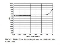
That is great. Should not be any penalty THD/N wise.
Enclosed a picture from the:
http://www.analog.com/media/en/techn...ets/AD1896.pdf
The signal can be attunated more than 6 dB before THD/N get worse.
I guess +6dB can be insertes on start of the DSP filters without the same risk of overload in the case of 2 (or more) way speaker.
In normal music the +0dBFS signal is a compound of different frequencies. Frequncy deviding gives very high probabillity for to sub 0dbFS signals.
As of the +8.6dB, SF/2 signal: Maybe a antialliasing filter attunates it enough to get under 6 dB? I dont know.
Thanks for again.
Regards Torgeir
Attachments
Last edited:
That is great. Should not be any penalty THD/N wise.
Enclosed a picture from the:
http://www.analog.com/media/en/techn...ets/AD1896.pdf
The signal can be attunated more than 6 dB before THD/N get worse.
I guess +6dB can be insertes on start of the DSP filters without the same risk of overload in the case of 2 (or more) way speaker.
In normal music the +0dBFS signal is a compound of different frequencies. Frequncy deviding gives very high probabillity for to sub 0dbFS signals.
As of the +8.6dB, SF/2 signal: Maybe a antialliasing filter attunates it enough to get under 6 dB? I dont know.
Thanks for again.
Regards Torgeir
The problem is that if you try and restore the levels in the proceeding sections such as the DSP or DAC then you risk overloading those stages which is what I observed.
cheers
OK, I see now what you have written in post #428. Was so sure the overhead bits in the DSP would handle it that it did't sink in.
Before the DAC then. +6dB on each output channel should be pretty safe when the signal is split in 4.
Or maybe there is enough gain in the output buffers to compensate?
Regards Torgeir
Before the DAC then. +6dB on each output channel should be pretty safe when the signal is split in 4.
Or maybe there is enough gain in the output buffers to compensate?
Regards Torgeir
OK, I see now what you have written in post #428. Was so sure the overhead bits in the DSP would handle it that it did't sink in.
Before the DAC then. +6dB on each output channel should be pretty safe when the signal is split in 4.
Or maybe there is enough gain in the output buffers to compensate?
Regards Torgeir
Well you can do that with extended precision or using floating point but then you have the problem of when you go out to the DAC which does not have the additional headroom.
The only way to fix it is to provide the extra 6dB of gain after the DAC on the analog side 😉
cheers
I agree that analog adjustment is the only 100% "safe" way to do it.
And there must also be 6dB headroom in the amps compared to sub 0dBFS material.
Then we where back to the days of headroom🙂
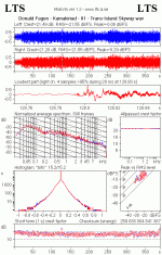
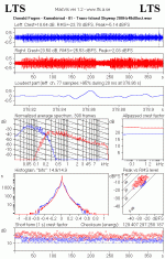
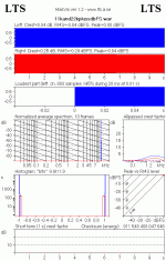
To illustrate the splitting of spectum point, I enclose two gifs.
It is the accumulated spectrum of Donald Fagen - Kamakiriad - Trans-Island Skyway done with MasVis
1st gif is both channels undevided. (No +0dbFS by the way)
2nd gif is left channel devided at 200Hz, 48dB/oct.
Low frequency channel: crest goes up. Has -5dB peak.
High frequency channel: crest goes down. Has -2dB peak.
And often the problematic portions of the songs is when the dynamics prosessor has pushed a HF signal modulated on a LF (bass) signal too close to 1 (0 dbFS sample value).
Remove the bass and it is OK.
And there must also be 6dB headroom in the amps compared to sub 0dBFS material.
Then we where back to the days of headroom🙂
To illustrate the splitting of spectum point, I enclose two gifs.
It is the accumulated spectrum of Donald Fagen - Kamakiriad - Trans-Island Skyway done with MasVis
1st gif is both channels undevided. (No +0dbFS by the way)
2nd gif is left channel devided at 200Hz, 48dB/oct.
Low frequency channel: crest goes up. Has -5dB peak.
High frequency channel: crest goes down. Has -2dB peak.
And often the problematic portions of the songs is when the dynamics prosessor has pushed a HF signal modulated on a LF (bass) signal too close to 1 (0 dbFS sample value).
Remove the bass and it is OK.
Attachments
Last edited:
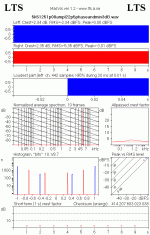
I see MasVis dont show +0dBFS signals.
But the crestfactor and RMS values is "unnatural" 😱 on the 11k and 22k +0dbFS signals posted earlier
The same with the 5k +0dbFS as the ordinary RMS value of a sine is -3dB.
Else it is an excellent program!
There may be other programs to find +0dbFS signals out there.
Sorry about the digression..
But the crestfactor and RMS values is "unnatural" 😱 on the 11k and 22k +0dbFS signals posted earlier
The same with the 5k +0dbFS as the ordinary RMS value of a sine is -3dB.
Else it is an excellent program!
There may be other programs to find +0dbFS signals out there.
Sorry about the digression..
Attachments
I see MasVis dont show +0dBFS signals.
But the crestfactor and RMS values is "unnatural" 😱 on the 11k and 22k +0dbFS signals posted earlier
The same with the 5k +0dbFS as the ordinary RMS value of a sine is -3dB.
Else it is an excellent program!
There may be other programs to find +0dbFS signals out there.
Sorry about the digression..
No this is great feedback and a real eye-opener !! I'm thinking this is the reason why SRC's may be given a bum rap by lots of people and which may have nothing to do with the sample rate change that most people attribute it too 😉
cheers
Last edited:
Thank you.
9 years on after tc electonics article and people still want bitperfect and oversampling... (Sorry for being sarcastic, took me 8 years to realise myself).
The industry is slowly taking it in. TV sound has become best in class for mass market. Loudness | TC Electronic
Even Apple recognices the the problem.
From end of page 4 in:
http://images.apple.com/euro/itunes/mastered-for-itunes/docs/mastered_for_itunes.pdf
One common process is called oversampling. This upsamples the digital data at fourtimes the original sample rate to improve the quality of the digital audio signal being converted to analog. If the original digital audio data is at 0dBFS, oversampling canresult in undesirable clipping. And if the original was already clipped, oversampling can make it worse. A growing consensus is emerging that digital masters should have a small amount of headroom (roughly 1dB) in order to avoid such clipping.
- Home
- Vendor's Bazaar
- Hi-end DSP based multi-channel integrated Preamp/Crossover/DAC project