BSST any new ideas ?Oscillation can sometimes produce strange behavior, including odd offset behavior.
I don't think believe you replied to this question. If this is the case, do you recall where the bias pot was positioned and can you return it to the same spot? Be careful--- too much bias current can cause damage.
You would probe amp output and look for signals that shouldn't be there. It might be insightful to monitor output with scope while you adjust bias current.
i have clean the board with flux cleaner on all nasty spots but still no succeed...
and yes of course you read the old pot before you put a new one and check that they have the same turn value 🙂
yes Q1=179mV Q2=182mV
And what is amp output DCV with the above transistor bias?
The base voltages suggest good offset matching of Q1/Q2, but the bias current is relatively large. These are old, obsolete transistors that had low Beta according to the data-sheet, but knowing amp output will give additional insight.
Dc output voltage across the big Capasitors?
Yes I run the bias staring at 570mV and it working its way upp to 600mV
Yes I run the bias staring at 570mV and it working its way upp to 600mV
When I measure bias on channel 1 I have COM on pin11 and V probe on pin10
And when I measure on channel 2 I have COM on pin21 and V probe on pin22
It's Fels like it should be reversed on channel 2 ?
And when I measure on channel 2 I have COM on pin21 and V probe on pin22
It's Fels like it should be reversed on channel 2 ?
Good ask. I prefer to always to keep black meter probe on ground and report voltages as signed numbers, eg. -400mV
From my schematic, pin 10 and pin 11 appear to be Gate 1 and Gate 2, respectively. Measuring between these points corresponds to measuring the "spreader" voltage, not what we need.
You should be measuring on the "O/P" signal, pin 6, or if more convenient either end of L1. Black meter lead should ideally be on SG, pin 4. Probing these two points should correspond well with speaker terminal voltages when the speaker relay closes. The objective in these measurements is to learn the voltage drops across bias resistors (eg. R1+R2, and R11) in order to determine bias currents in Q1 and Q2. My schematic is too marginal to read pin numbers in the other channel, but use corresponding points in the schematic for the other channel.
Since at one point you mentioned having high offset voltage in the good channel (CH 1?), would you recheck its output voltage, i.e. remeasure bases of Q1, Q2, and the amp output voltages.
Then remeasure again the same points in the problem channel.
Thanks!
i found the problem with the dc offset R24 whas open and R25 showing 21K . But when i replaced them i got in to another problem now i have over -40VDC on the speaker terminals and bias is 0V . i have try to adjust the pots with same value like channel one and some other positions bot they are nor responding,
neither on bias or offset.
any idea what can cause this ?
neither on bias or offset.
any idea what can cause this ?
It seems like you've had a mishap and possibly have a damaged part, maybe an open trace, etc.
Let's confirm that the offset control is in working order. Monitor the VR3 wiper terminal as you vary setting throughout its range. You should observe about +/- 2.7VDC variation. If this is the case, the VR3 pot is working. Set its position at center.
Please report voltages at base of Q6, base of Q7, and the output voltage observed at R31. It's likely about -40VDC based on reported -40V on speaker terminal. These readings will guide further voltage checks yet to come.
[You could look at base voltage of Q6 as you adjust VR3; you should observe a few tenths volt variation on the base. If so, the DC trim path is intact, sot set VR3 to mid rotation and we'll return to it eventually.]
every resistor and every diode is fine
this is the reading i get when i probe Ohm that are not the same as channel 2 when i compare with channel 1 .
Q10 0.45Kohm (red probe on E and black probe on C) Q6 0.63Mohm
Q10 0.45Kohm (red probe on C and black probe on E) Q6 Lo
Q10 3.3Kohm (red probe on B and black probe on C) Q6 0.6Mohm
Q10 3.3Kohm (black probe on C and red probe on B) Q6 Lo
Q8 0.8Kohm (red probe on C and black probe on E) Q3 0.6Mohm
Q8 Lo (red probe on E and black probe on C) Q8 Lo

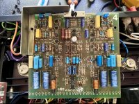
Hi mate,you have a totally different type of M900 there,i have 6 of them and all the same...your one is missing parts badly,check my PCB in the photo,the strange fact is that the pcb serial is the same... HH AS00097....never had any issues with mine,checked on scoope as well,also you should never got -40vdc on outputs as the dc detect should disconnect the outputs,this amplifiers use the protect relays opposite the normal operation like the rest of amplifiers.
Attachments
- Home
- Amplifiers
- Solid State
- HH MOSFET M900 DC offset 267mV when pot twisted to max?