i have set the bias on both Channels to 600mv
and set dc offset on Channel 1 to 0 mv
problem when offset stays at 267 mv when the trim pot is turned to maximum on Channel 2 ?
and set dc offset on Channel 1 to 0 mv
problem when offset stays at 267 mv when the trim pot is turned to maximum on Channel 2 ?
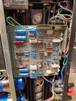
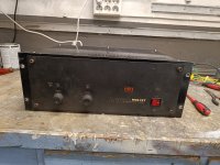
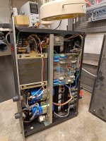
Attachments

rayma may be spot on.
I presume you are adjusting VR2. Does output respond to VR2 adjustment, i.e. can you make output voltage worse, but not better? To confirm viability of the pot, would monitor the wiper as you adjust--- it should adjust between about +/- 2.7V
Assuming the pot is OK, set it back to max as before and please measure voltages at bases of Q6 and Q7 and reconfirm output at +267mV. Also measure voltage across R30. Ideally, it will be 0mV, but any voltage across it is evidence of leakage through C15 and might be the cause. If the input pair was perfect, 4.7mV of leakage showing on R30 would give 267mV offset. i.e. 4.7uA leakage.
Last edited:
Pot is fine , Shall I measure between ground and base off Q6 Q7 ?rayma may be spot on.
I presume you are adjusting VR2. Does output respond to VR2 adjustment, i.e. can you make output voltage worse, but not better? To confirm viability of the pot, would monitor the wiper as you adjust--- it should adjust between about +/- 2.7V
Assuming the pot is OK, set it back to max as before and please measure voltages at bases of Q6 and Q7 and reconfirm output at +267mV. Also measure voltage across R30. Ideally, it will be 0mV, but any voltage across it is evidence of leakage through C15 and might be the cause. If the input pair was perfect, 4.7mV of leakage showing on R30 would give 267mV offset. i.e. 4.7uA leakage.
thanks for providing me.Yes, please measure as described in second paragraph of post #5.
Thanks!
Base of Q6= 1.024 V
Base of Q7 = 1.027V
DC offset Cannel 2 = 618mV
How do i measure across R30? one probe on cathode and the other probe on anode of the resistor ?
ESR is not the same as leaky. If not through C15, where else can the 5uA of current be flowing?
Confirm that the "3G" terminal really is at ground voltage. I still suspect C15, but perhaps some other path of contamination. That 5uA current is flowing somewhere.
Confirm that the "3G" terminal really is at ground voltage. I still suspect C15, but perhaps some other path of contamination. That 5uA current is flowing somewhere.
Last edited:
- Home
- Amplifiers
- Solid State
- HH MOSFET M900 DC offset 267mV when pot twisted to max?