They won't fit the window.
You need to allow for insulation between the primary and secondary and between the primary and EI.
Consider the same between secondary and EI.
Allowing that insulation leaves ~60% to 70% of the window available for copper.
your 16mm by 48mm window leaves you with <=540mm² for copper.
It's what I said way back,
and I had to repeat it for Pafi.Stacking the core thicker than the width moves one towards running out of window area.
Agree with wire not fitting that window.
And you can't simply match wire area to window area, because wire is round (so less efficient) instead of square or rectangular.
The Real World calculation considers space occupied by wire *as if* it were square , said square having sides equal or larger to actual wire diameter (including enamel) plus at least 10-15% waste because wire does not perfectly fill the layer plus something many do not consider: wire layers, if sectioned, can be seen as NOT being perfect rectangles with parallel sides but "ovals* , if you get what I mean, wire does not turn perfect 90 degree bends at corners , this is also wasted space.
Personally I fill windows to the brim, no kidding, but to do so I *must* press wire against the core with a hydraulic press or at least hammering it through a piece of hardwood to straighten that ovalized rectangle into a better fittingn one.
You need *at least* 1 mm free between wire and laminations, or it's relatively easy to scratch insulation and short the transformer.
Add layer to layer insulation, plus primery/secondary one, and you end up, as stated above, with around 70% useful window area.
In your case forget EI 125 (what you are using) and go 1 step higher, to EI 155 , with its 38mm center leg, or 155E, with its 42 mm center leg, obviously stacking less of it.
Both suggested laminations have way more window area than what you are trying to use now, the first one will barely fit (and that being careful and pressing as I suggested) , the second one will allow more relaxed home winding.
At that power range, using a very thick stack of EI 125 is justified *only* if you want to maximize power while still fitting the transformer inside a 2U rack cabinet, where it will barely fit (88 mm maximum external size allowed), I have seen even ridiculous 80-90mm stacking on Korean stuff, ; in any other case going to a larger lamination and approaching square stack is the way to go.
Or split the job and use 2 transformers, one for each channel 😉
LOL! Surprise! Do you know how many sizes has a bobbin or a core? You quite misleaded the ones tried to answer your question before.Hi
MY EI core size is 32mm*60mm
Roughly, and assuming core quality is appropriate - whatever it means, and window utilisation is OK too.giving 368 W maximum power.
I want to make 30 0 30 5A secondary out from transformer. according to my calculation dual winding of 75 turns for 30 0 30 V if i want another 25 0 25 V 5A from same winding with same center tap.Can it possible after dual 62 turn to take wire out for 25 0 25 V and continue up 75 turn which will give 30 0 30 final out from secondary.(Note that I will not use both voltage rail at same time).
following diagram for better understand my question
Yes, absolutely possible, but to design it optimally you have to specify the kind of the load. Is it a bridge rectifier with symmetrical load, or is there any asymmetry?
The numbers of turns can be OK, but core quality is unknown, so I recommend to test it. For testing you dont need to build a full primary. A few turns of testing coil made from flexible wire is perfect, and you dont need the full stack either, half or quarter of it is enough. Of course low AC voltage must be connected, for example 12V with 100 turns and 3rd stack. Indication of saturation can be done by connecting divided current signal to speaker and listening. Turn nr can be modified easily without disassembling the core and without wasting wire in order to find the exact V/turn limit, while you listen to the distortion in the sound.
They won't fit the window.
...
Stacking the core thicker than the width moves one towards running out of window area.
It's what I said way back,and I had to repeat it for Pafi.
Yes, it wont fit the window. And what if he used a thinner stack? Will it fit? No, it would be even worse, since more turns would be needed.
Repeating something 4 times or more doesn't make it true nor relevant. It had already disproven both in theory and in practice. Repeating is quite useless.
Last edited:
Also an important question is what will you use it for? Amplifier, lab PSU, accumulator charger etc... If amplifier, then what kind of? Class A, B, D? Bridged or SE? What will be the maximal ambient temperature? Can there be forced cooling? Will the transformer be touchable?
In practice these parameters all can affect the design very much!
If you are lucky, you can use your core without any problem (with a little thinner wire).
we knew that his requirements for power will not fit the winding window many posts back,
either he lowers his power demand and use smaller gauge wires or else use a bigger core...
either he lowers his power demand and use smaller gauge wires or else use a bigger core...
Also an important question is what will you use it for? Amplifier, lab PSU, accumulator charger etc... If amplifier, then what kind of? Class A, B, D? Bridged or SE? What will be the maximal ambient temperature? Can there be forced cooling? Will the transformer be touchable?
In practice these parameters all can affect the design very much!
If you are lucky, you can use your core without any problem (with a little thinner wire).
very good comment....we tried to give this hint to him earlier on...
Hi
MY EI core size is 32mm*60mm giving 368 W maximum power.I want to make 30 0 30 5A secondary out from transformer. according to my calculation dual winding of 75 turns for 30 0 30 V if i want another 25 0 25 V 5A from same winding with same center tap.Can it possible after dual 62 turn to take wire out for 25 0 25 V and continue up 75 turn which will give 30 0 30 final out from secondary.(Note that I will not use both voltage rail at same time).
following diagram for better understand my question
this is a question you do not ask here, you know your winding window,
you know the traverse width, you know what what wire size you want to use...
compute the number of turns per layer, compute the number of layers,
then knowing the number of layers and the diameter of your wire,
you will know the coil build up....do this for both the primary and secondary coils...
now compare the total coil build up with the winding window height...
if the number is more than 80% then you are in trouble,
go for the next smaller wire gauge and compute again...
less than 80% is good to go...
@sanbadgujar,
500 circular mil per ampere is what i typically use for selecting wire size.
although some builders use as low as 300 to higher than 700cm per ampere..
and if the results of your computation as per the above post is unacceptable to you,
then you either lower your expectations or use a bigger core...
Can it possible
Hi
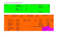
I found Excel calculation sheet for transformer on this site. I put my data
in it and found useful can it achievable. Attach with my datasheet.
Practical Transformer Winding
Hi
I found Excel calculation sheet for transformer on this site. I put my data
in it and found useful can it achievable. Attach with my datasheet.
Practical Transformer Winding
Attachments
Last edited:
😎500 circular mil per ampere is what i typically use for selecting wire size.
..
this is what I use for SMPS transformers too ( no forced air )
Last edited:
Practical Transformer Winding
A wise man. No reason to fix such parameters without consideration, just like current density, center leg/hight, fill factor, temperature, etc.
I recommend to read the whole page.
I have seen many text books giving design equations that result in a flux density of 1 Tesla in each and every transformer you calculate by them, like if that were a sacred rule! If you come across any such book, BURN IT! It's nonsense!
LOL...i used that calculator too...but i use it just for comparison than anything....
i know what i want and knows how to get it...😉

Thanks for that.
656 circular mills (c.m.) is roughly equivalent to the old guide of 3.1A/mm²
700c.m. ~ 2.82A/mm²
500c.m. ~ 3,95A/mm²
300c.m. ~ 6.58A/mm²
I'm an old fashioned Builder and stick to 3.1A/mm² for 50Hz transformers.
smps (50kHz to 200kHz requiring very thin wire) work with much high current densities. I have heard as high as 12A/mm²
That layout looks familiar. I found it a few years ago after a link here.Hi
I found Excel calculation sheet for transformer on this site. I put my data
in it and found useful can it achievable. Attach with my datasheet.
Practical Transformer Winding
It and all the others (reliable) I found all use the (core area)² for the core power capability.
There were a very few that got that part wrong.
Last edited:
- Home
- Amplifiers
- Power Supplies
- Here is the Computation of EI core Transformer Philippines Base