a 3000 watt traffo will have a 2.25 inch center leg stacked to 4.5 inches...
finished traffo will weigh in at around 45 pounds estimated...
@Techpolice,
3inch center leg core is available from Golden Mars, in Raon....
so that a 3 x 3.5 inch core section will get you there...
winding window will also be larger and you can maximize
copper wire size...
reposting here: posted by PRR, 21st June 2003, 04:20 AM
the thread....here
> How deep can you stack the laminations?
Magnetically: as deep as you like.
But for a good transformer, you want the most iron area with the least length of copper.
Assume you want a 1 square inch core and consider several core shapes and the length of turn in the first layer:
Round: 1.128" diameter, 3.54" turn
Square: 1" square, 4" turn
2:1 Rectangle: 0.707"x1.414", 4.24" turn
4:1 Rectangle: 0.5"x2", 5" turn
I have only computed the "first turn", not the average MLT. I'm lazy. But the trend will be the same all the way up the winding.
There are ways to make round cores, but they cost a lot.
With flat-stack laminations, square is best but a 2:1 stack is only 6% more copper loss, and even a 4:1 stack is only 25% worse than square-stack (assuming all the same wire gauge). Aim for square, but don't let it get in the way if you need a core area that is in-between standard EI sizes, or if you have to fit a certain space.
> is it necessary to isolate with paper (or what have you) the winding layers?
The voltage between adjacent turns, on 50/60Hz windings, is usually about 0.1V Volts. The varnish is good for over 100 volts. There is no reason to further insulate adjacent turns (obviously, or else magnet wire would have beter insulation).
Where you get in trouble is when you wind a layer then come back with a second layer. The voltage between start and finish is the sum of the per-turn voltages. If you are winding 20 turns per layer, it is 20*2*0.1= 4 Volts, no problem. But if you are winding fine wire on a wide core it could be a thousand turns, 1000*2*0.1= 200 volts, and you might want to slap some fishpaper between windings. Check your actual voltage per turn values from the design; "0.1V" is just my rough rule of thumb. It does not vary a huge amount for wall-power or audio transformers or chokes; it will often be less. But if you have a super-hot core iron and run it in heavy flux you may have more. And if you design for 400Hz or higher (aircraft systems, inverters) you better do the math even for very few turns per layer.
You also need insulation between windings if there is any large voltage (chokes don't matter unless they are dual-winding common-mode blockers). Wall-power should always be heavily insulated from the output winding. Tube plate output transformers have a large DC voltage added to the audio swing and normally want extra insulation so the B+ does not land on the guy touching the speaker terminal.
> paper (or what have you)
I am sure you know that "paper", ordinary paper, is only a little better than nothing, and worse if it wicks moisture into the winding. I don't know if you can still buy good-old "fishpaper", the classic 1930s inter-winding stuff, but I would use a heat resisting plastic film today.
the thread....here
nice to see that the best EI material can be run as high as 1.5T.....................way to do things is to use the best iron commercially available ................... from VERY good Russian made sheets,.......................
Routinely use them at 15000 Gauss (1.5T .................
I also design around square stacks.
There I minimize on copper cost.
...............................
And that square stacks ( the central core of the EI is near square) are the way to build right.
1.5T on M6 or M3 cores are fine as long as you don't run your traffo to saturation under load...
since traffo primary has a fixed number of primary turns and a fixed idle current, ampere-turns increases with load and with it the flux...proceed with caution....
since traffo primary has a fixed number of primary turns and a fixed idle current, ampere-turns increases with load and with it the flux...proceed with caution....
EI transformer question
Hi All
I want design transformer of 250 watt I have EI core bobbin size 4.5cm*3.8cm how to select secondary wire gauge if i want 30 0 30 6A on output of transformer.can consider gauge for 6A or 3A.If I consider 6A 60v*6A=360W or 30V*6A=180w. please help.
Hi All
I want design transformer of 250 watt I have EI core bobbin size 4.5cm*3.8cm how to select secondary wire gauge if i want 30 0 30 6A on output of transformer.can consider gauge for 6A or 3A.If I consider 6A 60v*6A=360W or 30V*6A=180w. please help.
I think you should be designing your primary FIRST !
When you have that part of the design completed and tested, you will find that the secondary is easy.
If you aim for a target efficiency of 94%, then the 250VA (output at the secondary) transformer needs a primary that takes 250/0.94 = 266VA.
For a supply voltage of 230Vac you need the primary to pass 1.16Aac
@ 31.A/mm² you need a cross section of 0.373mm²
0.7mm diameter copper gives 0.3848mm²
How many turns of that wire will fit into half your window area?
Will those turns give sufficient inductance to operate at a sufficiently low core flux without saturating?
The table on the right seems to be using ~3A/sqmm for the copper windings.
Modern transformers seem to use a higher current rating to save money on the copper in return for lower performance.
Modern transformers you think are toroidal with higher iron performance, much lower wire length, lower thickness of winding and higher effective cooling area, this because higher current density is allowed while they also perform better.
Hi All
I want design transformer of 250 watt I have EI core bobbin size 4.5cm*3.8cm how to select secondary wire gauge if i want 30 0 30 6A on output of transformer.can consider gauge for 6A or 3A.If I consider 6A 60v*6A=360W or 30V*6A=180w. please help.
india uses 230 volts 50hZ right?
so:
1 3/8 x 1 3/4 inches good for 198 va....
primary is 720 turns of # 24 awg wire,
secondary is bifilar 94 turns of #19 awg wire...
note that in india, british swg is standard,
so make your adjustments accordingly...
scrapless cores are assumed....
If you aim for a target efficiency of 94%, then the 250VA (output at the secondary) transformer needs a primary that takes 250/0.94 = 266VA.
For a supply voltage of 230Vac you need the primary to pass 1.16Aac
@ 31.A/mm² you need a cross section of 0.373mm²
0.7mm diameter copper gives 0.3848mm²
How many turns of that wire will fit into half your window area?
Sorry but this method is basically wrong.
There are 2 strategies, designing for allowable temperature, and designing for given drop.
(Allowable) current density should be calculated from trafo geometry, Bmax and allowable temperature rise. These 3 parameters also determines maximum power rating, based on this the apropriate core can be selected. From geometry and Bmax V/turn can be calculated, hence turn nr is approximately given. Wire cross section area must be chosen to fit window evenly. Now you can calculate wire resistance, drop. If it is acceptable, then you can adjust secondary number of turns according to drop. Otherwise a bigger core is needed.
Design for drop: for a given core (geometry and Bmax) drop is given, proportional to power. You can chose a core which is apropriate in these aspect. Calculate number of turns and wire length! Based on length and resistance(calculated from drop) a wire cross section can be calculated. Done.
Tables with permissible power and drop should be provided by core manufacturer, but can also be calculated with more or less precision.
We at least agree that the primary has to be designed first.
AJT got it.
The EI core is already fixed, he does not need to find a different EI.
what's the difference between my statement andWill those turns give sufficient inductance to operate at a sufficiently low core flux without saturating?
One has to get the primary ampere turns right before one can proceed.designing for allowable temperature, and designing for given drop.
(Allowable) current density should be calculated from trafo geometry, Bmax and allowable temperature rise. These 3 parameters also determines maximum power rating, based on this the apropriate core can be selected. From geometry and Bmax V/turn can be calculated, hence turn nr is approximately given. Wire cross section area must be chosen to fit window evenly. Now you can calculate wire resistance, drop. If it is acceptable, then you can adjust secondary number of turns according to drop. Otherwise a bigger core is needed.
Design for drop: for a given core (geometry and Bmax) drop is given, proportional to power. You can chose a core which is apropriate in these aspect. Calculate number of turns and wire length! Based on length and resistance(calculated from drop) a wire cross section can be calculated.
AJT got it.
design the primary first. But 24awg is a bit thin for 266VA primary. 21 or 21½awg suits better if 720 turns fits 50% of the window.primary is 720 turns of # 24 awg wire,
The EI core is already fixed, he does not need to find a different EI.
Last edited:
We at least agree that the primary has to be designed first.what's the difference between my statement and One has to get the primary ampere turns right before one can proceed.
Please forget ampere turns! I didn't tell anything about it, for a good reason. You don't need to calculate magnetic force.
If you mean just turns, then my answer is: 1 reason: nr. of turns can be calculated easily, no need for guessing current density. V=4.4*n*A*Bmax*f. (SI units.) 2nd reason: do you know what sufficient inductance is? Generally it is unknown. Depends on too many factors, and basically unspecified. You already experienced recently that it depends also on measuring voltage.
And your method is unfinished. You told 94 % efficiency, but I can't see how do you plan to check if it is achieved, or even viable. What if there is not enough turns fit in? What if inductance is "high enough"? Can you say you found the correct value? No, because resistance can be too high. Probably it will be in this case too. You said core is chosen, but you didn't use any parameter of it. How can you tell if it's appropriate or not?
Last edited:
Andrew!
You said core is chosen, but you didn't use any parameter of it. How can you tell if it's appropriate or not?
BTW:
You didn't calculate ampere*turns, neither AJT.
Bmax is about 1.1 Tesla in that table.
Magnetising current is not increasing with load. (Actually it is decreasing a little.) When you load a trafo, primary and secondary magnetising forces are pointing to the opposite direction, and magnitudes are almost perfectly equal. Magnetic balance makes a trafo: trafo. This is because it is so sensitive for DC. A very small current is enough to go saturation (and for DC there is no cancellation on the other side). If magnetic effect of primary current wasn't cancelled by secondary current (multiplied by turns of course) in the core, then a tiny load would have drived it to saturation.
You said core is chosen, but you didn't use any parameter of it. How can you tell if it's appropriate or not?
BTW:
You didn't calculate ampere*turns, neither AJT.
Bmax is about 1.1 Tesla in that table.
since traffo primary has a fixed number of primary turns and a fixed idle current, ampere-turns increases with load and with it the flux...proceed with caution....
Magnetising current is not increasing with load. (Actually it is decreasing a little.) When you load a trafo, primary and secondary magnetising forces are pointing to the opposite direction, and magnitudes are almost perfectly equal. Magnetic balance makes a trafo: trafo. This is because it is so sensitive for DC. A very small current is enough to go saturation (and for DC there is no cancellation on the other side). If magnetic effect of primary current wasn't cancelled by secondary current (multiplied by turns of course) in the core, then a tiny load would have drived it to saturation.
Last edited:
Sorry but this method is basically wrong.
There are 2 strategies, designing for allowable temperature, and designing for given drop.
(Allowable) current density should be calculated from trafo geometry, Bmax and allowable temperature rise. These 3 parameters also determines maximum power rating, based on this the apropriate core can be selected. From geometry and Bmax V/turn can be calculated, hence turn nr is approximately given. Wire cross section area must be chosen to fit window evenly. Now you can calculate wire resistance, drop. If it is acceptable, then you can adjust secondary number of turns according to drop. Otherwise a bigger core is needed.
Design for drop: for a given core (geometry and Bmax) drop is given, proportional to power. You can chose a core which is apropriate in these aspect. Calculate number of turns and wire length! Based on length and resistance(calculated from drop) a wire cross section can be calculated. Done.
Tables with permissible power and drop should be provided by core manufacturer, but can also be calculated with more or less precision.
agreed, for me it is temperature rise that is priority, coming from a very warm country.....
Andrew!
You said core is chosen, but you didn't use any parameter of it. How can you tell if it's appropriate or not?
BTW:
You didn't calculate ampere*turns, neither AJT.
Bmax is about 1.1 Tesla in that table.
Magnetising current is not increasing with load. (Actually it is decreasing a little.) When you load a trafo, primary and secondary magnetising forces are pointing to the opposite direction, and magnitudes are almost perfectly equal. Magnetic balance makes a trafo: trafo. This is because it is so sensitive for DC. A very small current is enough to go saturation (and for DC there is no cancellation on the other side). If magnetic effect of primary current wasn't cancelled by secondary current (multiplied by turns of course) in the core, then a tiny load would have drived it to saturation.
if i do not know the source and therefore the class of core, i just assume it to to be lowest grade, H50....
magnetizing current is not increasing with load, the primary ampere-turns is...
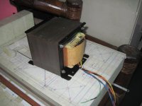
here is my recently built traffo using H50 cores, no load testing showed 60mA no load current,
and 15 watts of core loss, and with 9kgs of core material, that is 1.6 watts per kilogram...
with an effective radiating surface of about 59 sq inches, this traffo is running cool...
core is a 1 3/4 inch center leg with 4 inch stack....
will do short circuit testing shortly....
Attachments


magnetizing current is not increasing with load, the primary ampere-turns is...
This is true, but flux is determined by the sum of primary and secondary ampere*turns (=magnetising force = magnetising ampere*turns). (Note: pimary and secondary currents flow the opposite direction.) A core doesn't care which is primary which is secondary, current is current.
But actually we can't measure current at such high precision that is needed for telling flux. Instead we can tell flux from the fact that it induces voltage. Induced voltage equals to no-load voltage * (1 - primary drop), so (main) flux must also decreased with (resistive) load.
here is my recently built traffo
Looks nice!
here is my recently built traffo using H50 cores,
nicely done, looks 1st rate.
do you use any special impregnating sauce recipes for tropical climates?
This is true, but flux is determined by the sum of primary and secondary ampere*turns (=magnetising force = magnetising ampere*turns). (Note: pimary and secondary currents flow the opposite direction.) A core doesn't care which is primary which is secondary, current is current.
But actually we can't measure current at such high precision that is needed for telling flux. Instead we can tell flux from the fact that it induces voltage. Induced voltage equals to no-load voltage * (1 - primary drop), so (main) flux must also decreased with (resistive) load.
Looks nice!
and i guess there is no point to being too precise, being in the ball park is good enough for me......😉
nicely done, looks 1st rate.
do you use any special impregnating sauce recipes for tropical climates?
i use the clear air drying polyurethane varnish where i dip(submerge)
the traffo for about 15 minutes, then pull out to drip, then back in again in a
process that takes almost an hour....
then under the hot manila sun to dry, takes about a week...
sun baking, these traffos get hot to about less than 50*C....
He already stated the EI core size.Andrew!
You said core is chosen, but you didn't use any parameter of it. How can you tell if it's appropriate or not?
............
And It gets him into the ballpark.
AJT appears to have used that core size to arrive at his suggested 720turns.
Last edited:
- Home
- Amplifiers
- Power Supplies
- Here is the Computation of EI core Transformer Philippines Base