Increasing the stacking thickness does not increase the window area.
Window area rules for the copper that one can get onto the core.
yes.....that is why we get the next bigger sized core to get a bigger winding window,
so that we can use bigger sized copper wires and so get higher powers...
IOW, there is always a limit with what we can do with a given set of cores...
i did a quick testing of MOT salvaged from a junked microwave oven....
i think that the data speaks volumes....
i think that the data speaks volumes....
Attachments
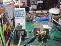
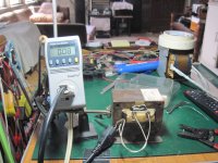

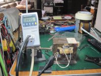
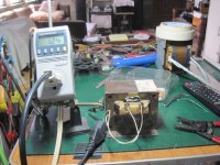

readings are line voltage, power factor, energy draw, real power draw, line frequency, magnetizing current.....
OK. I'll accept that.Please do not ignore the simple and most important law about transformers I mentioned many times: Faraday's law of induction, applied here: V/turn=Ae*Bmax*f*4.4 !
Completely wrong.Bmax is fixed, f is fixed, V is fixed, so if you increase Ae, then turn nr. will be decreased, thus wire cross section can be increased by the same factor. It's simple.
Double the area of Ae and you get quadruple the power capability.
Double the area of Ae and you get half the required Turns.
But the wire diameter needs to be doubled (4 times the cross sectional area) to be able to pass four times the current to match the current density of the smaller stack's lower VA.
Half the number of turns times four times the copper area will not fit the original size of window.
That's what I said way back
Stacking the core thicker than the width moves one towards running out of window area.
Completely wrong.
Double the area of Ae and you get quadruple the power capability.
??? What? Why? In what circumstances? What about the rest of the parameters? How did this came here? Has anybody stated this before?
Double the area of Ae and you get half the required Turns.
But the wire diameter needs to be doubled (4 times the cross sectional area) to be able to pass four times the current to match the current density of the smaller stack's lower VA.
Yes, 4 times more current on a 4 times more cross-section means the same current density. But did anybody say 4 times more current before? Absolutely not! 2 times more power => 2 times more current was the prediction for 2 times higher stack. Why do you deny something what is not stated?
Where?!?Half the number of turns times four times the copper area will not fit the original size of window.
That's what I said way back
Exactly what is wrong? In this post you didn't tell anything to be wrong in my statements. What you denied is contrary to my statements. I said "the same factor" not "2 times more of that factor".Completely wrong.
Last edited:
If one doubles the area of Ae, one gets a transformer with quadruple the power capability.
VA = Ae² *Bmax where Ae is in cm² and Bmax is in Tesla for metric units.
or
VA = 31*Ae² *Bmax where Ae in in in² for imperial units
If you only double the cross sectional area of the quadrupled power transformer you end up with double the current density in the windings.
I don't know much about transformers. But I know enough to recognise that you are trying to mislead us.
Last edited:
That's what I said way back
Quote:
Stacking the core thicker than the width moves one towards running out of window area.
Where?!?
If one doubles the area of Ae, one gets a transformer with quadruple the power capability.
Wrong. Read below! (And actually you've already proven it to be wrong.)
VA = Ae² *Bmax where Ae is in cm² and Bmax is in Tesla for metric units.
Absolutely not. There is no such equation. The dimensions are also wrong totally. (Hence you can know its wrong.) VA=cm^4*Vs/m/m ? No.
or
VA = 31*Ae² *Bmax where Ae in in in² for imperial units
Maybe somewhere you can find such dimensionally incorrect rule of thumb ignoring many factors, because they assume "usual" parameters. For example this assumes every sizes are proportional to each other. But the question we ask is exactly about the variation of ratio of 2 sizes. The question we search for the answer to is directly contrary to the assumption used by your rule of thumb, this because you can't use it to find the answer. (In a valid argumentation premises can't deny each other.)
Side note: your rule of thumb is not correct even with the fixed ratio assumption. It also needs the assumption of fixed current density which is a bad assumption if heating is accounted. I've already gave the correct relationship between size and power: P~a^3.5 while your rule of thumb implicitely states P~a^4. Not a big difference, but in large scale it becomes significant.
Basically you can not use a rule of thumb to falsify an exact calculation based on laws of physics and math. Assumptions can not override calculations.
I don't know much about transformers. But I know enough to recognise that you are trying to mislead us.
I understand you are frustrated because you don't know where were you wrong, but still this was rude and I refuse such malicious statement. I can show every calculations if you are still in doubt, however I think I identified the source of your misbelief.
You are misleaded by a not understood rule of thumb that can not be applied here.
Hi all
I think 45mm*38mm gives 292W maximum power. Therefor if i want 30 0 30 supply I have to down my current rating to 4A for secondary.
so for
primary winding 647 turn of 22 SWG (0.77mm) and
for secondary 84 dual turn of 17 SWG(1.4mm).its give me about 276 W is my calculation is right. my public supply is 230V AC.
sanbadgujar,
You should give us the size of your window.
Is it 2.0 cm by 6.0 cm. or is it 2.25 by 6.75 cm.?
If it is the latter you could wind your transformer for 30,0,30v 6A.(180VA)
If it is the former then you can wind it with SWG #17 but 84 dual turns
for 30,0,30v 4A (120VA).
Its not the core but the window limiting your requirement.
Srian.
i think that enough concepts have been expounded here already,
for anyone to be able to start making one's own traffos,
the rest is hard work.....and that is the fun part....
i am a diy'er and like building traffos more than talking....😉
for anyone to be able to start making one's own traffos,
the rest is hard work.....and that is the fun part....
i am a diy'er and like building traffos more than talking....😉
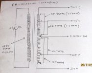
Can It is possible
Hi
MY EI core size is 32mm*60mm giving 368 W maximum power.I want to make 30 0 30 5A secondary out from transformer. according to my calculation dual winding of 75 turns for 30 0 30 V if i want another 25 0 25 V 5A from same winding with same center tap.Can it possible after dual 62 turn to take wire out for 25 0 25 V and continue up 75 turn which will give 30 0 30 final out from secondary.(Note that I will not use both voltage rail at same time).
following diagram for better understand my question
Attachments
Isn't it a bit short-sighted that you have used Ae² for your power capability calculation after Pafi has assured us that this is wrong !.........MY EI core size is 32mm*60mm giving 368 W maximum power...............
Your turns ratio 577:150 gives the open circuit voltage ratio.
i.e. 577Turns @ 230Vac gives an open circuit output voltage of 29.9Vac for 75Turns.
You now need to reduce this by the estimated transformer regulation value of this EI. Try using 8% for 368VA EI transformer.
i.e. output voltage ~29.9/1.08 ~= 27.7Vac when loaded with a resistor to draw the maximum design current.
Are the 0.82mm and 1.57mm the wire copper diameters, or the wire cross-sectional areas?
Is your window 16mm by 48mm?
Last edited:
Your turns ratio 577:150 gives the open circuit voltage ratio.
i.e. 577Turns @ 230Vac gives an open circuit output voltage of 29.9Vac for 75Turns.
You now need to reduce this by the estimated transformer regulation value of this EI. Try using 8% for 368VA EI transformer.
i.e. output voltage ~29.9/1.08 ~= 27.7Vac when loaded with a resistor to draw the maximum design current.
Are the 0.82mm and 1.57mm the wire copper diameters, or the wire cross-sectional areas?
Thank for your reply ,i will make changes according to your suggestion ,but is it OK to take multiple voltage from same secondary winding according to my posted diagram ?
Multiple taps are good.
Better if you do a multiple tap dual secondary.
No more wire, but a lot more flexible when you come to wire it up.
Better if you do a multiple tap dual secondary.
No more wire, but a lot more flexible when you come to wire it up.
What size is your window?
16 by 48mm,
or 30 by 90mm?
16 by 48 mm
equals 768mm² window area.
diameter or sqmm?
What size are those wires?Are the 0.82mm and 1.57mm the wire copper diameters, or the wire cross-sectional areas?
diameter or sqmm?
equals 768mm² window area.
What size are those wires?
diameter or sqmm?
values are diameter
- Home
- Amplifiers
- Power Supplies
- Here is the Computation of EI core Transformer Philippines Base