Lets go back to the original query by Sanbadgujar,
and AJT s reply,
and AndrewT's suggestion,
To find whether the window size is sufficient for the suggested coils lets calculate:
1.Sanbadgujar said his bobbin is 35mm. * 45mm.
therefore the center leg of his lamination stack is 35mm. wide.
For scrapless cores the
Window = (1/2*centerleg)*3(1/2*centerleg)
=17.5*52.5
which is about 920 square mm.
2.AJT says the secondary is bifilar 91 turns #19awg which is 0.9mm.
when this is squared and multiplied by two times 91 it gives the area
the secondary copper occupies.
0.9*0.9*2*91 sq.mm. = 147 sq.mm.
3.AndrewT suggests #21awg (0.72mm) 720 turns for the primary.
This will occupy 0.72*0.72*720 sq.mm. = 373 sq.mm.
4. Total copper of secondary and primary will be 520 sq.mm.
5.When we deduct this amount from the window area of 920sq.mm. the balance of about 400 sq mm is left for insulation and another winding if needed.
Therefore Sanbadgujar could wind his transformer 30v,0,30V on his core with suggested coil sizes.
Srian.
Hi All
I have EI core bobbin size 4.5cm*3.8cm how to select secondary wire gauge if i want 30 0 30 6A on output of transformer.
and AJT s reply,
india uses 230 volts 50hZ right?
so:
1 3/8 x 1 3/4 inches good for 198 va....
primary is 720 turns of # 24 awg wire,
secondary is bifilar 94 turns of #19 awg wire...
note that in india, british swg is standard,
so make your adjustments accordingly...
scrapless cores are assumed....
and AndrewT's suggestion,
But 24awg is a bit thin for 266VA primary. 21 or 21½awg suits better if 720 turns fits 50% of the window.
To find whether the window size is sufficient for the suggested coils lets calculate:
1.Sanbadgujar said his bobbin is 35mm. * 45mm.
therefore the center leg of his lamination stack is 35mm. wide.
For scrapless cores the
Window = (1/2*centerleg)*3(1/2*centerleg)
=17.5*52.5
which is about 920 square mm.
2.AJT says the secondary is bifilar 91 turns #19awg which is 0.9mm.
when this is squared and multiplied by two times 91 it gives the area
the secondary copper occupies.
0.9*0.9*2*91 sq.mm. = 147 sq.mm.
3.AndrewT suggests #21awg (0.72mm) 720 turns for the primary.
This will occupy 0.72*0.72*720 sq.mm. = 373 sq.mm.
4. Total copper of secondary and primary will be 520 sq.mm.
5.When we deduct this amount from the window area of 920sq.mm. the balance of about 400 sq mm is left for insulation and another winding if needed.
Therefore Sanbadgujar could wind his transformer 30v,0,30V on his core with suggested coil sizes.
Srian.
more often than not, the space computations are a bit tricky,
factors such as how tight or efficient you wind the coils come into play....
my little secret, i use one size lower than what was computed most of the time...😉
factors such as how tight or efficient you wind the coils come into play....
my little secret, i use one size lower than what was computed most of the time...😉
2.AJT says the secondary is bifilar 94 turns #19awg which is 0.9mm.
when this is squared and multiplied by two times 91 it gives the area
the secondary copper occupies.
0.9*0.9*2*91 sq.mm. = 147 sq.mm.
I find the suggested coil is too thin for the secondary current of 6A.
It should be #13awg (1.82mm.)
which will occupy about 623 sq.mm.
Then the total copper of secondary and primary will be 995 sq.mm.
Which is not possible to fit the window.
My suggestion is for him to wind this transformer 30V 6A.
and use a bridge rectifier.
Then he need not wind the secondary winding of the bifilar winding.
His core would be enough.
Srian.
or get a bigger core....
Agreed.
In such instances what I do is to find a little more of the same size
laminations and make the stack bigger.
split the bobbin and increase its size.
Re-calculate the number of turns which will be less now.
(bigger core - less turns, as turns per volt will be less)
Therefore the window will be enough to to put all the coil.
Srian.
EI calculation
Hi all
I think 45mm*38mm gives 292W maximum power. Therefor if i want 30 0 30 supply I have to down my current rating to 4A for secondary.
so for
primary winding 647 turn of 22 SWG (0.77mm) and
for secondary 84 dual turn of 17 SWG(1.4mm).its give me about 276 W is my calculation is right. my public supply is 230V AC.
Last edited:
Stacking the core thicker than the width moves one towards running out of window area.
That rough calculation (thank you, Srian) of 0.72x0.72x720 = 373mm² is a bit big for 50% of 920mm²
A rough guide to allow for insulation is ~60% to 70% of the available window. That leaves ~300mm².
i.e. use fewer turns (depends on the core material), or thinner wire (requiring less current).
Using a thinner stack gives a lower VA and that allows the thinner wire.
But the only way to find out is to wind on 720 Turns and see if it can be made to fit the 50% window. Then plot the Iprimary vs Vprimary and see how close to saturation that core gets with the maximum mains voltage applied. It's a lot of work if one finds that 720 Turns is too big and even more work if one finds that the core is many volts below saturation. But checking the used primary window area and plotting the Ip vs Vp does not require a secondary winding, so it's possible to go back and try a different primary.
Last edited:
Srian understands what is the basic of a transformer: flux changing. V=dB/dt*Ae.Stacking the core thicker than the width moves one towards running out of window area
Re-calculate the number of turns which will be less now.
(bigger core - less turns, as turns per volt will be less)
Therefore the window will be enough to to put all the coil.
But who wants lower VA? Higher VA was the requirement.Using a thinner stack gives a lower VA and that allows the thinner wire.
Last edited:
polyurethane varnish where i dip(submerge)
the traffo for about 15 minutes, then pull out to drip, then back in again in a
process that takes almost an hour.
Thanks
you probably have the oil based (alkyd) version, CA has moved to water based😡
thinking out loud ,you could probably build a small vacuum pump on 5 Gal metal storage bucket lid to speed things up.
put the regular lid back to storage.
Last edited:
Thanks
you probably have the oil based (alkyd) version, CA has moved to water based😡
thinking out loud ,you could probably build a small vacuum pump on 5 Gal metal storage bucket lid to speed things up.
put the regular lid back to storage.
yes, been toying with that for years, i will get to that soon....😎
yes, been toying with that for years, i will get to that soon....😎
single stage pump can be had cheaply or if have a good compressor you can get a super cheap vacuum attachment https://youtu.be/4-UlEuvwOxc

if the window area is not big enough then he is screwed. i.e. he is asking for too much power from the selected core.Srian understands what is the basic of a transformer: flux changing. V=dB/dt*Ae.
But who wants lower VA? Higher VA was the requirement.
He just has to face that fact.
The copper and the core area/flux determine the maximum VA.
The design has to take account of the copper and the core.
An ideal EI will have near square central core leg and have near equal copper volume in the primary and secondary.
Move away from these and the performance will drop.
power transformers for amplifiers are not so straightforward as it seems....
a power traffo that can supply 200 watts on a continuous basis, can supply 400 watts but on short duty cycle...
music into a speaker load as opposed to sine waves have far less energy content, than a sine wave power into a resistor load...
so it is really up to the designer to arrange his ducks in the sequence that he likes...😉
if the window area is not big enough then he is screwed.
As Srian pointed out and I will also explain below, power rating can be increased by bigger stack depth. Consider Faraday's inductance law and Ohm's law, along with geometrical dependancy of resistance and magnetic characteristics of iron!
An ideal EI will have near square central core leg and have near equal copper volume in the primary and secondary. Move away from these and the performance will drop.
Well, actually only performance/price ratio will drop a little. In transformers the bigger is better (unless it is totally screwd up, or the smaller uses much better technology, etc...), just more expensive.
so with a little more iron of the same shape and a little more copper you can achieve more power with smaller drop. As Srian pointed out well. For example: 2 times the stack thickness of an "ideal" (quadratic center leg) transformer, 40 % more copper makes a 100 % higher power rating with 30 % less drop! (Turn number is halved, wire cross section is doubled.) The "ideal" trafo with twice the power rating would be a 22 % bigger (in linear dimension) core, weighted 81 % more (copper also 81% more) and 26 % less drop.
(Note: I calculated dependancy of power and drop on linear size increasement on paper. If somebody is interested very much I could type the calculation, but the result is: P~a^3.5, and drop~a^-1.5, where "a" is the relative linear size increasement.)
So we can get to the conclusion: actually the optimal thickness/width ratio of a scrapless transformer is NOT 1, but somewhat more, somewhere between 2 and 1. (As we can see in most case of a good transformer.)
I don't know the exact number, and not really care, because a reasonable deviation from it makes very little additional cost in theory, and practically something you have is always cheaper than something you don't have. But it must be possible to calculate the ideal value also.
Last edited:
Increasing the stacking thickness does not increase the window area.
Window area rules for the copper that one can get onto the core.
Window area rules for the copper that one can get onto the core.
An ideal EI will have ... have near equal copper volume in the primary and secondary.
This is true as long as every secondaries are in use in the same time. But if one of them is resting in every half-period (as in case of +/- DC rectified by full bridge but loaded only between 1 rail and 0V, which is typical for single ended amplifiers driven at very low frequency), then only the active copper can be calculated. (Somebody mentioned something like this before.) But since adding copper to 2 secondaries needs twice as much reduction in primary, the optimal ratio is not P:S=1:2, but... I don't know, will calculate...
(x: occupation for primary related to window)
Rp= 1/x
Rs= 2/(1-x)
minimising R=Rs+Rp=1/x+2/(1-x):
dR/dx= ln(x)-2*ln(1-x)
dR/dx=0 => ln(x)=-2*ln(1-x), drawing... x=0.38, (P:S=0.38:0.62=0.61)
Actually because this happens purely only at very low freq, and audio is a mixed signal, the optimal primary occupation will be somewhere between 0.38 and 0.5.
I regularly modify the amp to draw symmetrical current, this way I can use x=0.5.
P.S.:
I ignored the fact that secondary turns are longer (but colder), this introduce some additional error, but nut much. Sorry for that.
Last edited:
Increasing the stacking thickness does not increase the window area.
Window area rules for the copper that one can get onto the core.
Please do not ignore the simple and most important law about transformers I mentioned many times: Faraday's law of induction, applied here: V/turn=Ae*Bmax*f*4.4 !
Bmax is fixed, f is fixed, V is fixed, so if you increase Ae, then turn nr. will be decreased, thus wire cross section can be increased by the same factor. It's simple.
Last edited:
power transformers for amplifiers are not so straightforward as it seems....
a power traffo that can supply 200 watts on a continuous basis, can supply 400 watts but on short duty cycle...
music into a speaker load as opposed to sine waves have far less energy content, than a sine wave power into a resistor load...
so it is really up to the designer to arrange his ducks in the sequence that he likes...😉
That's true. And because of this in home usage heating will not be the most severe limiting factor, but DC voltage drop.
PA at very high power and active crossovers can introduce overheating in case of designing for drop. But they are ClassD nowadays.
on stacking factor, RDH4 recommends 2 or else use a bigger sized laminate....
one important factor to consider: the quality of cores used,
this is also a deal maker...
i have several power traffos made in the past that i discarded due to heating issues,
these traffos are good traffos mind you, but just that people find heating as unacceptable...
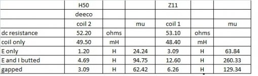
these traffos were built with H50 cores, since i got several kilos of RM18(M24) cores,
i am replacing the irons with RM18 ones, i have taken data readings as to no load watts lost,
so i can compare the results after the change....
below is the comparative inductance data with H50 vs, Z11(M6):
trend seems to indicate 3x better in terms of inductance,
but as always, downside is cost is 5 to 6 times more...
one important factor to consider: the quality of cores used,
this is also a deal maker...
i have several power traffos made in the past that i discarded due to heating issues,
these traffos are good traffos mind you, but just that people find heating as unacceptable...
these traffos were built with H50 cores, since i got several kilos of RM18(M24) cores,
i am replacing the irons with RM18 ones, i have taken data readings as to no load watts lost,
so i can compare the results after the change....
below is the comparative inductance data with H50 vs, Z11(M6):
trend seems to indicate 3x better in terms of inductance,
but as always, downside is cost is 5 to 6 times more...
Attachments
- Home
- Amplifiers
- Power Supplies
- Here is the Computation of EI core Transformer Philippines Base