the first channel has been working for half a day according to the new scheme from today's post:
https://www.diyaudio.com/community/threads/hennadys-take-on-the-1969-jlh.409972/post-7631043
I'm putting together a second channel. Everything is in the making...

https://www.diyaudio.com/community/threads/hennadys-take-on-the-1969-jlh.409972/post-7631043
I'm putting together a second channel. Everything is in the making...

Yes, you are right, we need to show everything, look here:I don't see where you installed very additional transistors.

Thanks Hennady
I have some of these pcb in my archives, do you think you could make an implementation diagram so that I can try to apply your modifications?
I have some of these pcb in my archives, do you think you could make an implementation diagram so that I can try to apply your modifications?
Yes, this is possible, but all the modifications have not been completed yet, it is possible to reduce the dependence of the increase in distortion on the increase in output power - a little later I will publish a solution that may surprise you (because there add is only 1 resistor.))))).Thanks Hennady
I have some of these pcb in my archives, do you think you could make an implementation diagram so that I can try to apply your modifications?
I calculated the rise rate in the latest version of the modification with "bridge compensation" SR = 20V/µs. !!!
I also agreed with a friend for a test comparison with the MX50 amplifier. They have the same NFB depth and number of amplification stages, only the power is different, but the difference of 16 watts of the “2024 modification” and 50 watts of the “MX50” is not so easy to distinguish by ear, but the tests will be at 4-6 watts of output power.
Now I’m putting together a second channel for this.
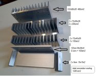
Here is the data for a set of convection radiators for 1 channel:
Attachments
Excuse me. What amplifier is MX50 based on? Its a pleasure to follow your mod/building.
Cheers!
Cheers!
I think the MX50 is a LJM amp(correct me if I'm wrong), there have been variants I think, like MX50SE, MX50x2 and maybe more. I have a few LJM MX50SE which are basic 'blameless' with CFP output. I usually use them to drive woofers, because they are simple and seem reliable, and have low output impedance because of the CFP output. My ears don't agree with the upper mid/treble from them.
Musical fidelityI think the MX50 is a LJM amp(correct me if I'm wrong)
I assembled the radiator (indicated the overall dimensions) and mounted the board into the radiator block, everything is in the attachment.


Yes, everything is correct as they wrote above, this is a set of LJM kits, it is considered as a simple high-quality HIFI. So let's listen.)))Excuse me. What amplifier is MX50 based on?
Thank you.Its a pleasure to follow your mod/building.
Cheers!
The sound quality depends on the operation of the input stage.My ears don't agree with the upper mid/treble from them.
simulating a further version of the JLH modification for bipolar power supply, I was faced with the fact that I cannot increase the output power by more than 25 W, the whole point is insufficient current for the Q2 driver transistor, and it not only must be increased, but it also must be precisely balanced according to in relation to the precision current node Q5Q6Q8 of the lower arm of the amplifier. As a result, resistor Radd1 appeared, the value of which should be equal to half the sum of the resistors in the collector Q2; resistor Radd2 was used to compensate the current of the drivers of precision current assemblies of power transistors. added, which was previously in the current sensor. Last time I removed it due to the high current of the power transistors (more than 1.3A), due to the high output current, strangely the sound deteriorated,
with the addition of Radd1 and Radd2, the initial current does not exceed 1 Ampere and the circuit parameters are the most optimal, and the sound is very good.
diagram with this modification in attachment.
The channel at my house is now working with this, I hope, the latest modification of such a simple circuit for single-polar power supply.
A very strange question arose - why is the resistor in the original JLH 1969 circuit rated at 2.2 kOhm? it’s not clear, because Most of the current of the driver transistor goes into the base of the power transistor, and what it is or what it is not with such a rating obviously does not affect anything. Maybe I’m not taking something into account, but that’s why I removed it, but when more than 25 watts of power was needed, this is where its rating is decisive. Moreover, even in this version of 16 watts of power, its presence with a certain rating benefits the sound.
I re-drew the diagram into a compact form, the values and designations of the elements coincide with the previous version of the diagram.
Last edited:
I received a question in the mail: why is there no inductor in the compensation bridge?
I answer: the “current dumping” compensation bridge works on the principle of equality (balance) of currents in the bridge between points B and D.
R8 was moved to the Q3Q4Q7 assembly base so that the Radd2 R17 current sensor became “floating” relative to point D, for this reason the bridge became more sensitive to changes in the current at point B, and the current through R8 is monitored by changes through the Q3 base. For this, no inductance is needed, because All cascades operate with large initial currents and in opposite directions - which is what is needed to form a compensation bridge.
If some cascade operated with zero quiescent current, then the coil would be needed to keep one half of the output stage switched on with its current until the opposite cascade is fully switched on (transition through the B-E voltage) - this is implemented in Quad 405/606/707/909...

The compensation circuit where R8 is transferred from the output of the circuit to the Base: will work only with unipolar power supply. For bipolar power supply, the balance of the bridge is formed differently - due to the equality of the currents of the driver stage and the output stage. Later I will show a variant of such an implementation.
To be continued it will be very interesting)))....
I answer: the “current dumping” compensation bridge works on the principle of equality (balance) of currents in the bridge between points B and D.
R8 was moved to the Q3Q4Q7 assembly base so that the Radd2 R17 current sensor became “floating” relative to point D, for this reason the bridge became more sensitive to changes in the current at point B, and the current through R8 is monitored by changes through the Q3 base. For this, no inductance is needed, because All cascades operate with large initial currents and in opposite directions - which is what is needed to form a compensation bridge.
If some cascade operated with zero quiescent current, then the coil would be needed to keep one half of the output stage switched on with its current until the opposite cascade is fully switched on (transition through the B-E voltage) - this is implemented in Quad 405/606/707/909...
The compensation circuit where R8 is transferred from the output of the circuit to the Base: will work only with unipolar power supply. For bipolar power supply, the balance of the bridge is formed differently - due to the equality of the currents of the driver stage and the output stage. Later I will show a variant of such an implementation.
To be continued it will be very interesting)))....
As promised, the option for bipolar power supply, with a power of 50 watts / 4 ohms.
I took the bipolar version of the 2003 JLH as a basis, increased the supply voltage level and added complementary mofets (side).
Oddly enough, the "compensation bridge with current dumping" fits very well, here the initial current flows through the L1 coil for linear operation and is additionally shunted by a 2-ohm resistor R15 - this resistor does not affect the operation of the compensation bridge, it only improves the transient characteristics, because . We have a complementary stage at the output and without this resistor there are emissions at the fronts.
The bridge has reduced distortion by 10 times. The output stage M1M2 itself operates with an initial current of 330 mA, M1 current is added through the coil.
The output voltage is set using trimmer X1. The output voltage is no more than 1 uV.
For the operation of the "compensation bridge", namely capacitor C5, it is necessary to reduce the bandwidth of the stable current generator Q1Q2. This is done by capacitor C3. Using R10, you can adjust the initial current of the output stage; it should be greater than that of the Q7Q8 stage and so that the current through the coil should not be more than 10% of the current of the complementary output stage.
What we get as a result:
*The total thermal dissipation power is 30 watts, which approximately corresponds to the 1969 JLH version.
*output power into a 4-ohm load is 54 watts
*symmetrical limitation
*distortion is minimal, mainly the 2nd harmonic.
*the scheme of VAS JLH is practically unchanged,
Finally, using an example of a model, I was able to show how a “current dumping” bridge is formed for a complementary cascade on mosfets. Its influence on quality is very strong - it reduces distortion by 10 times, while only the 2nd harmonic remains - this is the result of the initial current through the L1 coil.
using coil L1 without an initial current leads to large amplification nonlinearity.
Attached are all the simulation results:
Last edited:
Interesting to see your ideas based on the JLH!
The original 69 was the first amp I played around with and started to learn simulations, and also the basics on transistor amps some years ago. The simplicity and nice sound made it appealing. It still has a place in my heart, just like the first girl I fell in love with as a kid 🙂
I hope you can make some measurements once you have settled on a concept you like. In addition to the standard measurements I would personally be interested in some multitone FFT's at different levels.
30 watt dissipation for 54 watts out means ~62% efficient? -Well not for music and lower volume, but still?
Cheers!
Cheers!
How is it with distortion? IMD is the most impairing for sound quality? Can this be measured and isn't it more relevant than THD?
Cheers!
Cheers!
Thank you!Interesting to see your ideas based on the JLH!
I understand your hopes, hope and my capabilities; many friends with measuring equipment have left (in connection with the war) or are engaged in a slightly different, more military matter, i.e. obviously not by measuring amplifier characteristics. The war will end, everything will be!!!I hope you can make some measurements once you have settled on a concept you like. In addition to the standard measurements I would personally be interested in some multitone FFT's at different levels.
The reason for the increase in efficiency is precisely the need to reduce the temperature dependence of sound deterioration.30 watt dissipation for 54 watts out means ~62% efficient? -Well not for music and lower volume, but still?
A bipolar transistor has an optimal current - and this is not class A current, of course they can be paralleled, but conceptually this is a different approach.
54 watts is the DIN power for a 4 ohm active load; this load in the impedance of the speaker system occupies 10-20 percent of the entire frequency response band. The effective power is a maximum of 70% of the DIN power, the average listening power is even less.
Here's an example of the JBL acoustic impedance measured in an audio studio

It is even more important to understand under what conditions these same distortions appear. IMD distortions consist of the frequencies of parasitic harmonics of the signal lying in the region of the rapid decay of the amplifier's frequency response - in this amplifier the pole is at a frequency of 22 kHz with a NFB depth of 45 dB, and the feedback enters the low-impedance input of the input transistor (emitter) - this is the fastest NFB that can be in a topology, which is why they do it this way, to avoid IMD distortion)))).How is it with distortion? IMD is the most impairing for sound quality? Can this be measured and isn't it more relevant than THD?
IMD is considered in differential input stages, but not in current feedback...
The next important source of IMD distortion is output power transistors operating in severe thermal conditions of class A, when their parameters strongly depend on temperature.
In general, IMD distortion is important only not in such a topology.
The second channel is ready.
How nice it is to solder, connect, and it works in the given modes and you don’t need to adjust anything.
Next I will make a board to secure both channels since they are located in the housing. with all connectors and wiring tracking.


How nice it is to solder, connect, and it works in the given modes and you don’t need to adjust anything.
Next I will make a board to secure both channels since they are located in the housing. with all connectors and wiring tracking.
Conceptually, I probably don’t even remember what the JLH 1969 sounded like (it was 1990), it didn’t last long due to the fact that there was no suitable radiator. But I remember for sure that the phase inverter pipe did not “breathe” like the current MODIFIED version,I hope you can make some measurements once you have settled on a concept you like.
But the 2003 JLH version is well known to me as it sounds, in fact, I remade it due to the fact that the sound still didn’t suit me, even when it was warming up, and it was heating up very much, and the current was about 1.7 amperes per channel when powered +/-25 volts.
in fact, here is a photo of it converted into 4 pairs, to reduce the influence of temperature on the sound.


Last edited:
- Home
- Amplifiers
- Solid State
- Hennady's take on the 1969 JLH