Talk about going round in circles!
I posted some comparisons of risetimes for different transistors back in 2020 (post #7215 in this thread).
Like the mods to the Chinese kit by the way. Though ST stopped making 2N3055's recently, but the date code looks OK (unless the codes are fake).
(They still sell a TIP3055 in plastic).
I posted some comparisons of risetimes for different transistors back in 2020 (post #7215 in this thread).
Like the mods to the Chinese kit by the way. Though ST stopped making 2N3055's recently, but the date code looks OK (unless the codes are fake).
(They still sell a TIP3055 in plastic).

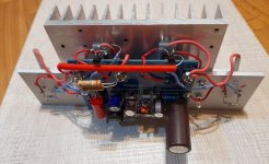
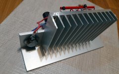
The channel is ready
turned it on, it worked)))
voltage 27 volts
the current was 1.6A, adjusted/reduced to 1 Ampere
as the current decreases, it sounds even better subjectively.
Well, as I said - a distinct elastic and full bass.
we can say that the modification “pump up” bass sound.
The radiator temperature is 52 degrees and does not rise.
In principle, everything is clear to me - the modification is working - when using modern power transistors - the layout of the new board will not increase in size from the one in the kit.
Last edited:

use them.I found them at my storehouse, maybe these ones have very high heat conductance (I saw they have about 100x more heat conductance than silicon pads) and helps smaller heatsinks? Should I use or sell them ( if they are expensive I can sell them )
I installed these - everything is ok, normal.
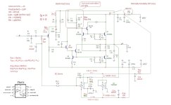
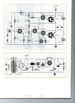
Modification diagram that I assembled
output power at 27 volts of supply voltage at a load of 4 ohms is 16 watts, with a power supply of 32 volts the output power is 25 watts.
The amplifier has retained the linearity of the open loop gain in the audio frequency range (ultralinear), the pole is at a frequency of 26 kHz, the open loop gain is 53 dB, the gain of open loop Q1 has increased from 8.5 dB to 15 dB, and the gain of Q2 has decreased to 38 dB.
The output transistors operate in class A(super A) and, in the presence of a R20||R22 current sensor and transistors Q6Q5, can increase the current in excess of the load when the signal is large.
In the attachment on the diagram I wrote down all the relationships of the elements to obtain the maximum parameters of the scheme.
The dual resistors in the circuit are connected bifilarly.
Last edited:
If you break them and release dust this is highly toxic, so I'd smear in thermal grease to prevent such dust being released if the worst happens. Add a warning sticker too. BeO is better than many metals at conducting heat. There are probably regulations about shipping BeO products, so use them responsibly instead?
Hello!
A logical continuation of the modification is getting rid of the output capacitor. To do this, it is necessary to use a bipolar voltage source.
For a power transformer, the most common voltage on the windings is 2x12 volts of alternating voltage, when rectified under load it will be +/- 16.8...17.5 volts, we will design a modification for this voltage.
Analysis of the modification proposals shows the illogicality of using a stable current source from the positive power bus to the emitter of the input transistor, because in this case, the amplifier does not receive current from the output of the amplifier and the amplifier loses the combination of current and voltage feedback as in the original JLH 1969. The stability of the amplifier design will depend on the stability of this current source.
Also, the use of a stable current source in the load of the driver transistor eliminates the appearance of surprise sound, because the tracking connection through a passive circuit, resistors and a capacitor have a complex frequency response with a high quality factor at a frequency of 1-3 kHz and a sharp decrease in resistance at a frequency of 5 kHz and above.
The active current source has a wide band from hundreds of kHz to tens of MegaHz, which eliminates the signature sound of the original JLH 1969.
see Attachment.
I tried to take into account the negative impact from stable current sources, so I suggest using a servo.
Attached is a project with calculations of time constants that determine the minimum impact of the DS servo on the circuit parameters.
In DS servo, I suggest using a dual microcircuit, because the second half of the microcircuit does not participate in amplification and its passive current consumption, equal to the current consumption of the active element, stabilizes the voltage.
modification diagram for the bipolar version, taking into account as much as possible the features of the circuit of the original JLH 1969, see the attachment below.
Attachments
if anyone is interested only in distortions on the 1st watt))) , on slow slow old-school power transistors, look at the attachment

First of all, congratulations on your dedicated work.
🙂
However, it would be great if you could carry out and document real-life measurements, apart from the well-known game with "Micro-Cap 12" (which I also use, among other things).
Regards,
HBt.
Psst. Are you a member of the Sukov gang?
🙂
However, it would be great if you could carry out and document real-life measurements, apart from the well-known game with "Micro-Cap 12" (which I also use, among other things).
Regards,
HBt.
Psst. Are you a member of the Sukov gang?
Thank youFirst of all, congratulations on your dedicated work.
🙂
However, it would be great if you could carry out and document real-life measurements, apart from the well-known game with "Micro-Cap 12" (which I also use, among other things).
Necessarily. I purchased a very simple kit for self-assembly to check the performance and most importantly the sound style of the modification in the super A class. I have never heard such bass from JLH either in the 1969, 2003 or 2005 versions, or in the modification with increasing pairs of output transistors.
I will assemble the second channel in a more compact form, and then I will convert it into a bipolar version - it’s actually simple - remove the output capacitor, disconnect the tracks for the negative power terminal and connect the chip on the operational amplifier.)))
Psst. Are you a member of the Sukov gang?
and who is it? I don’t know who Sukov is.
After comparative listening on a speaker system with a full-range speaker and a reference two-way speaker system, the difference in sound was very noticeable.
If you look at the diagram, the source of such a difference turned out to be two topology nodes - the input filter R1C1 and the load circuit R14R15 C7 for driver Q2 with tracking chain connection via C7.
The fact is that I now have R14 = R15, and this is true provided only the active load resistance and without taking into account the nonlinearity of the impedance. In fact, this turned out not to be the case, and increasing the impedance at the upper frequencies of a real speaker system significantly affects the subjective perception of sound.

Having simulated the tracking circuit separately from the circuit, it turned out that I have a center frequency of 4.5 kHz with a low quality factor. If you look at the original circuit from 1969 and the compiled table of R1R2 C1 values, it is easy to notice the relationship between the values of this circuit and the load resistance. With a load resistance of 8 Ohms, the center frequency was 3.3 kHz, with a load resistance of 3 Ohms - 2.5 kHz.

Having tried various variants of the parameters of the tracking circuit in the model, I came to the conclusion that none of the options provided good transient response, however, with increasing the quality factor, the transient response still improved, so I continued to increase the quality factor relative to the center frequency of 3.3 kHz to the moment when the transient response ceases to depend on the load. And we got these values:
R14 = 10 Ohm
C7 = 470 µF
R15 = selected in the range of 200....820 Ohm for the circuit current consumption of 1A for output power transistors and 1.3 Amperes in general for the circuit, the current value in my modification does not depend on the load resistance.
Next is the input filter R1C1 - the situation is such that without it (as in the 1969 original) there is a problem with the transient process, but even with it the transient process also turned out to be unsatisfactory.
The best option turned out to be the R1C1Radd circuit as in the diagram below.
In general, these are the settings you get.

I myself am confused by such a low resistance of R14 = 10 ohm , today I will check how justified it is.
If you look at the diagram, the source of such a difference turned out to be two topology nodes - the input filter R1C1 and the load circuit R14R15 C7 for driver Q2 with tracking chain connection via C7.
The fact is that I now have R14 = R15, and this is true provided only the active load resistance and without taking into account the nonlinearity of the impedance. In fact, this turned out not to be the case, and increasing the impedance at the upper frequencies of a real speaker system significantly affects the subjective perception of sound.
Having simulated the tracking circuit separately from the circuit, it turned out that I have a center frequency of 4.5 kHz with a low quality factor. If you look at the original circuit from 1969 and the compiled table of R1R2 C1 values, it is easy to notice the relationship between the values of this circuit and the load resistance. With a load resistance of 8 Ohms, the center frequency was 3.3 kHz, with a load resistance of 3 Ohms - 2.5 kHz.
Having tried various variants of the parameters of the tracking circuit in the model, I came to the conclusion that none of the options provided good transient response, however, with increasing the quality factor, the transient response still improved, so I continued to increase the quality factor relative to the center frequency of 3.3 kHz to the moment when the transient response ceases to depend on the load. And we got these values:
R14 = 10 Ohm
C7 = 470 µF
R15 = selected in the range of 200....820 Ohm for the circuit current consumption of 1A for output power transistors and 1.3 Amperes in general for the circuit, the current value in my modification does not depend on the load resistance.
Next is the input filter R1C1 - the situation is such that without it (as in the 1969 original) there is a problem with the transient process, but even with it the transient process also turned out to be unsatisfactory.
The best option turned out to be the R1C1Radd circuit as in the diagram below.
In general, these are the settings you get.
I myself am confused by such a low resistance of R14 = 10 ohm , today I will check how justified it is.
Last edited:
Thank you. This is an error in drawing the polarity - the polarity is not indicated in the model, but on the board the polarity of the capacitor is indicated correctly.Small detail: check the polarity of C7, it should be inverted.
Yesterday I spent the whole evening listening on speaker systems to various options for resistor ratios in the driver load circuit with a tracking link R10R11C6.
As a result, the best ratio turned out to be an equal ratio of resistors R10=R11 in this circuit. (see attachment)
The solution to the R1R2C1 input circuit also turned out to be very effective, while in the 1969 original there was no such circuit at all, and in later versions the RC turned out to be ineffective for improving the parameters.
The problem with the subjectively audible dependence of the sound on the impedance of the speaker system was solved by increasing the current to 1.3A.
As a result, the modification circuit for a unipolar supply voltage took on the following form:

In general, the "RRC" load circuit with a tracking connection for a single-cycle driver (VAS) is very interesting for an audio solution and probably forgotten with no justification (you can remember the solution in the Quad-405/606/707/909 amplifiers). The use of a stable current source in this node reduces the measured distortion, but at the same time the proportion of high harmonics in the distortion increases significantly. Those. it turns out that what is important is not the minimum value of distortion, but the relative level of the second in relation to other harmonics and THD distortion was not more than 0.04%.
If you look at the distortion of the 2024 version modified by me, then at the first watt it is 0.02%. The maximum power was 16 watts into a 4 ohm load.
More promising is the option with bipolar power supply and DC servo, because allows you to get rid of the input capacitor and the capacitor in the NFB circuit - this will reduce distortion by 3 times.
As a result, the best ratio turned out to be an equal ratio of resistors R10=R11 in this circuit. (see attachment)
The solution to the R1R2C1 input circuit also turned out to be very effective, while in the 1969 original there was no such circuit at all, and in later versions the RC turned out to be ineffective for improving the parameters.
The problem with the subjectively audible dependence of the sound on the impedance of the speaker system was solved by increasing the current to 1.3A.
As a result, the modification circuit for a unipolar supply voltage took on the following form:
In general, the "RRC" load circuit with a tracking connection for a single-cycle driver (VAS) is very interesting for an audio solution and probably forgotten with no justification (you can remember the solution in the Quad-405/606/707/909 amplifiers). The use of a stable current source in this node reduces the measured distortion, but at the same time the proportion of high harmonics in the distortion increases significantly. Those. it turns out that what is important is not the minimum value of distortion, but the relative level of the second in relation to other harmonics and THD distortion was not more than 0.04%.
If you look at the distortion of the 2024 version modified by me, then at the first watt it is 0.02%. The maximum power was 16 watts into a 4 ohm load.
More promising is the option with bipolar power supply and DC servo, because allows you to get rid of the input capacitor and the capacitor in the NFB circuit - this will reduce distortion by 3 times.
Last edited:
Your amplifier has discrete compound transistors (Darlington) at its output (Q5+Q7 & Q6+Q8). The first transistor (Q5\Q6) operates in pure class A. The second (Q7\Q8) one operates in class AB with a large initial current (1a). Hence the increase in higher harmonics compared to the original 1969 circuit.
This is not pure A class - A+AB.
Similar solutions were used in the 1960-1970s.
This is not pure A class - A+AB.
Similar solutions were used in the 1960-1970s.
Attachments
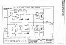

yesYour amplifier has discrete compound transistors (Darlington) at its output (Q5+Q7 & Q6+Q8).
yes, that's right, this class is also called "super A", I wrote about it in another topic, these posts did not get here.The first transistor (Q5\Q6) operates in pure class A. The second (Q7\Q8) one operates in class AB with a large initial current (1a)....
This is not pure A class - A+AB.
the current sensor R18/19 is important for the transition to class AB
Hence the increase in higher harmonics compared to the original 1969 circuit.
harmonic growth only when the output power increases during the transition to A + AB (super A)
I'm sorry, but there is only class A in your attachment.Similar solutions were used in the 1960-1970s.
and if you take TIP141, then the first transistor in the Darlington assembly works in the "easy" current mode.
In my case, it is necessary to pump the input capacitance of the old-school power transistor.
PS the goal of the modification is to squeeze the maximum out of the low-voltage power supply, while remaining in Class A up to "the 1st watt", it is possible to do so according to Lin's topology or symmetrical (Hiraga), but then you will not get a clean second harmonic.
Last edited:
- Home
- Amplifiers
- Solid State
- Hennady's take on the 1969 JLH