Hi,
19db of EQ slaughters the max SPL from the speaker.
That is almost 100times boost the get bandwidth extension.
At the frequencies where the signal returns to flat the maximum signal is reduced to just 6.3W. If you listen at about 20db below maximum peak levels, the SPL for average listening is what the speaker can generate from 63mW (I guess about a whisper).
Redesign the speaker to significantly reduce the EQ.
AndrewT said:
Redesign the speaker to significantly reduce the EQ.
Hi Andrew,
With all due respect, you don't seem to understand one of the main advantages of an LT - that's to drive the speaker below it's resonant frequency where impedance is flat. In order to do this, you carefully design a box size that will push Fs up above the frequency band the speaker will be driven at.
19 db of boost at 20Hz is quite normal for an LT.
AndrewT said:MJ,
read my post again.
I have, and it's not telling me anything new.
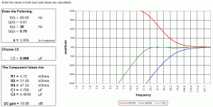
Shown below are the spreadsheet calculations for the LT, based on my Unibox model that determined the volume of the box will be 60 litres to drive the Fsc up to 60Hz. This sub is meant to do it's work below 60Hz.
In real life (as this is working and with me now), it doesn't slaughter the SPL. It works exceedingly well, as a matter of fact.
Attachments
MJL21193 said:
Unibox model that determined the volume of the box will be 60 litres
Mistaken memory: box size is actually 100 litres. I went back and checked.
😱
Hi MJ,
you are using LT with 19.08db of EQ to bring up the out of band response to match the speakers in band frequency response.
Let's take a couple of hypothetical fiqures.
Sensitivity 90db/W in the passband of the speaker.
Response 19db down at the required extended low frequency.
result after applying the LT is constant frequency response down to 20Hz (F(p) from your table) instead of flat to 60Hz (F(0) from your table.
The max SPL will be limited by the Xmax of the speaker and the heat dissipation of the VC and the 500W amplifier.
The speaker when driven at just above 20Hz will have your +19.08db of EQ and when driven at about 60Hz have 2.5db of EQ and further up the frequency range 0db of EQ.
Lets now look at the SPL available at these frequencies.
In the high range with 1W of input we get 90db SPL @ 200Hz.
At 60Hz with 1.8W we get 90db SPL.
At 20Hz with 81W we get about 88db SPL.
Now let's turn our attention to the other drivers.
Assume they too are 90db/W.
They will be set up to produce the same SPL for the same input signal to give that desired flat frequency response. 1W will give 90db SPL.
Lets now increase the volume for a peak transient signal.
The 500W amp can do an extra 7.9db or about 96db @ 20Hz.
With a flat frequency response, 60Hz is about 98.4db
and the upper range will also be 98.4db
Average level is usually chosen to be 20db below these levels to leave headroom so that peaks are not clipped.
The result is that you have 76db@20Hz, 78.4db@60Hz and 78.4db@upper frequency range.
Now what power do we need to listen to 78.4db on a 90db speaker? About 69mW gives your average level and the amp needed for this leaving that 20db of headroom is 6.9W.
See what I mean about "slaughtering the max SPL" capability.
Most LT design programmes warn about the consequence of choosing to use high EQ to extend the low frequency pass band beyond reason. One octave is usually maximum, half an octave is more common, you have gone for 1.5octaves.
That's why I said "Redesign the speaker to significantly reduce the EQ".
If I've got any of this wrong then please come back.
edit.
the box volume is irrelevant to these SPL comparisons.
It's the excessive EQ that reduces the peak SPL capability.
Getting back to the subject, I am looking for suggestions for higher voltage, high gain input transistors. Already suggested were ZTX694B and ZTX795A by Spind in the SymAsym thread. These are available to me from Digikey (though they are pricey at ~$1.80 each). Are these good enough to justify the high price?
Other suggestions? Or should I just stick with a lower voltage unit and either cascode or drop the voltage in the input stage?
Here are the Zetex ones:
http://www.zetex.com/3.0/pdf/ZTX795A.pdf
http://www.zetex.com/3.0/pdf/ZTX694B.pdf
Other suggestions? Or should I just stick with a lower voltage unit and either cascode or drop the voltage in the input stage?
Here are the Zetex ones:
http://www.zetex.com/3.0/pdf/ZTX795A.pdf
http://www.zetex.com/3.0/pdf/ZTX694B.pdf
MJL21193 said:Getting back to the subject, I am looking for suggestions for higher voltage, high gain input transistors. Already suggested were ZTX694B and ZTX795A by Spind in the SymAsym thread. These are available to me from Digikey (though they are pricey at ~$1.80 each). Are these good enough to justify the high price?
Other suggestions? Or should I just stick with a lower voltage unit and either cascode or drop the voltage in the input stage?
Here are the Zetex ones:
http://www.zetex.com/3.0/pdf/ZTX795A.pdf
http://www.zetex.com/3.0/pdf/ZTX694B.pdf
Can't drop the input stage voltage, that would reduce the maximum output voltage pro rata.
2sc1775, 2sc1845, 2sc2240, 2sc2362, 2sc2547, 2sd756 etc. bc546c
AndrewT said:
If I've got any of this wrong then please come back.
edit.
the box volume is irrelevant to these SPL comparisons.
It's the excessive EQ that reduces the peak SPL capability.
Hi Andrew,
Your analysis, as usual, is very thorough. It does make perfect sense.
In real life it's another thing altogether. For an average size room, you don't need more than 96db at 20Hz. There is also the matter of room gain.
I know, from practical experience, that what I say above is true. In it's present configuration, with the 500 watt amp, the low frequency reproduction is more than adequate.
What's more, the amp has a steady, easy load to drive.
Box volume has to do with the tuning frequency of the sealed box. Making it bigger (a LOT bigger) will lower the tuning frequency of the enclosure. Once again, this is not desirable, as the amp will see the big impedance peak at this lowered Fsc.
If you have room gain then you don't need 19.08db of EQ.MJL21193 said:.......... For an average size room, you don't need more than 96db at 20Hz. There is also the matter of room gain........
96db was peak transient. Listening level would be around 76db.
That is not loud it just about matches a normal conversation.
80db is getting loud, 90db is LOUD but that needs a peak transient capability of 110db and that in turn would require 12.5kW of amp power and what kind of speaker could survive that?
Reset your F(p) to 40Hz and see if the EQ is reduced to less than 12db. <10db would be better.
if you could get down to 9db of EQ, you would immediately add 10db to your peak SPL and add 10db to your average listening level for the occasion when you require to "turn it up a bit".
Now it would be much more realistic.
If you were to change the speaker parameters to produce a gently falling response rather a flat response you could then USE your room gain to bring up the low bass and use the EQ to extend it out another half to three quarters of an octave. That would get you closer to what I think you could achieve.
AndrewT said:
Listening level would be around 76db.
That is not loud it just about matches a normal conversation.
80db is getting loud, 90db is LOUD but that needs a peak transient capability of 110db and that in turn would require 12.5kW of amp power and what kind of speaker could survive that?
Andrew, you don't need anywheres near 1250 watts:
"Note that the maximum gain is over 18dB - this is rather high, but the energy levels at such low frequencies are actually very low as well, so although it may seem that an enormous amount of power will be needed, this is probably not really true in reality."
The above is quoted from Rod Elliot's ESP site here:
http://sound.westhost.com/project71.htm
I can attest to the fact that in reality what he is saying about power requirements is true.
To increase the power of the low frequency response from my subwoofer, I'd run the risk of structural damage to my house.
It certainly can be LOUD.🙂
AndrewT said:
Don't go ClassB...
For a possible high power sub woofer amp...
I have reconfigured my final circuit for class B operation. I have changed the gain to 37 (from 30) to keep the input sensitivity normal (1.22 Vrms). I have also replaced the transistors in the cascode and differential pair to the higher voltage BC546B. Switched to a complimentary output with 4 extra devices (using MJL21193/94 here).
Results are excellent (for a subwoofer amp)
At 70 volt rails:
494 watts into 4 ohms ( enough output devices?)
329 watts into 6 ohms ( my woofers actual Re)
247 watts into 8 ohms
THD at <100Hz is .002%. Compare to the simulation of the one I have now (ESP project #68) which is .152% THD.
I need a good reason not to use class B if these are the numbers I can expect. If it is used exclusively for low frequency, I don't see a problem.
Here's what it looks like:
Attachments
Hi John,
Q6 and Q7 really need to be a higher voltage type, and they're not a critical function. They cover most of the rail voltage. The diff pair and mirror do not need to be high voltage when set up like this.
That output stage is patented by Bryston IIRC, usually not a problem to copy for non-profit research purposes.
I've not tried it myself.
Did you try the same devices set up just as emitter follower for a comparison? And what about pure CFP?
What are you trying to gain with class-B? Avoiding the thermal feedback? Wouldn't you want to listen to the amp full range just to hear it? I think you'd want AB then.
You asked about bridging earlier. For many years I looked at bridging as a hack to get more power. However, there is an advantage regarding power supply ripple, and bridging is essentially like putting the output devices in series which often provides better SOA.
When you sim at 56 or 70V is this the voltage you assume that your supply will droop to under full power load? Or do you plan to use a very stiff supply?
Let's say you want something like 350W into 8 ohms which typically requires 100V rails, or 50V for a bridged or balanced amp. Now, look at the SOA for your output devices, what is the V * A at 50 V, as compared to 100V. Many modern devices rated as 200W are 100W at 100V and around 150W at 50V. Thus, it is better to put them in series. BJT's do not like high voltage due to secondary breakdown.
There were some very old designs that put the output devices in series, and even today this provides better SOA.
Pete B.
PB2 said:Hi John,
Q6 and Q7 really need to be a higher voltage type,
Did you try the same devices set up just as emitter follower for a comparison? And what about pure CFP?
What are you trying to gain with class-B? Avoiding the thermal feedback? Wouldn't you want to listen to the amp full range just to hear it? I think you'd want AB then.
Hi Pete,
A lot has happened since your last post, including this little side-track about subwoofers.
I could use MPSA42 to replace Q6 & Q7.
In the simulation for the real amp being designed here (remember that one? 🙂 ), I tried the MJL21193/94 but found distortion was higher than the MJL4281A/4302A. But it's the other way around for the complimentary output, with poorer results from the MJL4281A/4302A. Not entirely sure if this is a valid result.
I've tried only the Bryston output stage in this amp. I may try other options, but I really can't expect better results than I'm getting now.
When Andrew said avoid class B, I had to try it, just to see how bad it would be. For a subwoofer, I can't see a reason to go AB.
The other amp here, I will listen to at full range (though the end use for this may be for a pair of ripole woofers, for music).
PB2 said:You asked about bridging earlier.
...Or do you plan to use a very stiff supply?
I like the idea of bridging, but have looked at it like this: people balk at class B due to crossover distortion, but this distortion can be quite a bit more in a bridged approach. Potential for 4 times the power is a mighty incentive though.
I am going to bridge two in simulation to see the results.
I have a 40-0-40 750VA transformer for the AB amps, using as much as 20mF per rail. Will this sag under the (stereo) load?
The transformer running the sub amp is 800Va 50-0-50. It has 10mF per rail right now. I have not measured it under load.
Hi,
I built a Leach clone powered from 40+40Vac and got 311W into 4r0.
It has three pair (Jens' smaller PCB) and +-45mF per channel.
I built a Leach clone powered from 40+40Vac and got 311W into 4r0.
It has three pair (Jens' smaller PCB) and +-45mF per channel.
MJL21193 said:
Hi Pete,
A lot has happened since your last post, including this little side-track about subwoofers.
I could use MPSA42 to replace Q6 & Q7.
In the simulation for the real amp being designed here (remember that one? 🙂 ), I tried the MJL21193/94 but found distortion was higher than the MJL4281A/4302A. But it's the other way around for the complimentary output, with poorer results from the MJL4281A/4302A. Not entirely sure if this is a valid result.
I've tried only the Bryston output stage in this amp. I may try other options, but I really can't expect better results than I'm getting now.
When Andrew said avoid class B, I had to try it, just to see how bad it would be. For a subwoofer, I can't see a reason to go AB.
The other amp here, I will listen to at full range (though the end use for this may be for a pair of ripole woofers, for music).
Take a look at the VAS collector signal voltage while supplying about 5V out in the class B design. You should see it compensating for the crossover distortion.
I suggest 10 ohm base stoppers for all the outputs. CFPs are a bit more fussy it seems. I do like CFP by the way.
You might want to look at the driver current, clipped under short circuit conditions. With and without the stoppers.
MPSA42 is very low beta, 2N5550 is much better, they only see one rail or 70V worst case in your latest design.
C9 is shorted in your latest.
Pete B.
Transformers can have an effective source impedance of anywhere from .5 to 2 ohms typically for audio transformers.
Its easy to put a dummy load and draw say 1A then 5A or even 10A to get the load line and then compute the effective resistance to use in simulation. You need large high power resistors obviously.
You might want to try a simulation with 1 ohm in series with the supply and say 10,000 to 20,000 uF. Drive it at 20Hz and view the supply voltage.
AndrewT said:Hi,
I built a Leach clone powered from 40+40Vac and got 311W into 4r0.
It has three pair (Jens' smaller PCB) and +-45mF per channel.
I looked at the leach amp, but it's too weighed down with unnecessary components. Also, I also don't like the symmetrical approach. I prefer to keep it as sparse as possible.
311 watts from 56 volt rails is pretty high? I can't sim that much without clipping from this supply (on the above circuits). Could it be my circuits are "eating" some voltage?
What are the output devices used?
- Status
- Not open for further replies.
- Home
- Amplifiers
- Solid State
- Help with this amp? A patchwork product of simulation