AndrewT said:I don't think so.
As stated in my previous post most transistors start to turn on at around 400mV not 600mV.
They are in their normal operating range when Vbe ~=600mV.
I said *about* 600mV. If at all, at 400mV the transistor will only be conducting very slightly. At this point it may begin to introduce distortion, but it won't effectively begin clamping the VAS current until significantly higher.
Cheers,
Glen
Hi Glen,
We'll put the diodes aside for the moment, as I think I have the problem solved.
Is it possible that by raising the current in the VAS, Q4 will not reach saturation? I have noticed that clipping is controlled above 20 KHz now that the current has been increased.
The addition of a resistor on the collector of Q13 limits the current in the VAS during clipping.
It's playing out very nicely on the simulation right now.
I will post an updated schematic shortly.

Okaaayyy....... This is a bit embarrasing, but we have all been getting ahead of ourselves here by a long shot.
One thing that hasn’t been mentioned yet (I am a bit guilty here too) is that it is NOT rail clipping which will cause the VAS current to skyrocket – there must be somewhere for the excess collector current of the VAS to flow.
Current limiting of the VAS is only generally needed if the output stage is also current limited with a clamping circuit (which typically diverts the VAS current to the load). In the basic unprotected “D.Self” topology such as yours, it really isn’t necessary.
Q4 will saturate of when the output voltage rails out in the positive direction, but the Q6 will still only draw from the VAS the small base current it needs to maintain the peak output current through the load.
That’s why your amp is working fine in simulation. If your output stage was I-limited, and was driven to "clip" at a lower output voltage into a excessively low impedance load, then that would be another story.
Cheers,
Glen
MJL21193 said:Here it is. Less is more maybe. What I have is ~11mA through the VAS, increases to 23mA with +3Vpp on the input (total 6.38 Vpp). Less than 2Vdc at the base of the drivers (both positive and negative).
Low distortion across the board.
The VAS given that it is an 8A device is not the issue at this point anyway.
Let me give you this to think about, what is the power dissipated in the 1K that you put in the collector load? Remember I suggested a 5.1K.
Answer this: what is the max current in Q13 during clipping?
Pete B.
PB2 said:
Answer this: what is the max current in Q13 during clipping?
With the input signal increased by 3 Vpp to 6.38 Vpp, current through Q13 measures as 16mA. 3.38 Vpp input (and below) 2mA. I wasn't looking at Q13, my mistake.
I'll change R22 to 5K.
Pete, what is your theory on the clamping action I'm seeing now?
That seems to be the very problem I'm suggesting we avoid.G.Kleinschmidt said:I said *about* 600mV. If at all, at 400mV the transistor will only be conducting very slightly. At this point it may begin to introduce distortion, but it won't effectively begin clamping the VAS current until significantly higher.
If the protection transistor starts to turn on (=injecting extra current from the rail to EF or VAS base) then that will add to the current the LTP is asking for. This extra current is not sent in proportion to the audio signal. It switches on at a voltage trigger (i.e. non-linear) and must cause distortion.
So, I go back to my original statement, the protection must not trigger on valid audio signals.
To avoid this the trigger voltage that causes the protection transistor to start turning on must be set such that 400mVbe or so is never reached with a valid audio signal going through the VAS.
We are not just talking about feeding max power into a resistive simulated or real test load either.
The worst case output current for a valid audio signal can be as bad as Vpk/Rload/0.35 or nearby. This peak current ripples through the amplification process with hFE current gain at each stage.
I think that a margin of safety is allowed for this peak current if the protection transistor starts to turn on at two times VAS quiescent current producing that 400mVbe of trigger voltage. That is the same as saying three times VAS current causing 600mV of trigger voltage.
I suspect that these sim models have been missing this point and the protection is triggering much earlier than anticipated. Maybe the simulator is detecting that the protection transistor is starting to turn on at an even lower voltage than 400mV. If the sim is doing this, could the transistor model be wrong or should we be aiming for 300mV trigger voltage for two times VAS quiescent current?
Once we know what the trigger voltage should be, we can work towards calculating the failure/overload/clipping/IV limiting conditions and what current power passes the EF and VAS during the fault condition and then size them to survive these new exceptional conditions.
AndrewT said:So, I go back to my original statement, the protection must not trigger on valid audio signals.
Well of course it shouldn't - if you back to my first post in this issue you will see that I quite plainly said exactly the same thing.
I was explaining how the preferred VAS current limiting circuit works, not endorsing this particular execution.
Cheers,
Glen

R21 looks too high to get the output biassed to any sensible current. Maybe around 300r.
The cascode driven by r28 looks interesting. Did it show on the sim?
I don't understand R36. That would seem to modulate the voltage on the LTP tail, changing the LTP current with output voltage. As output goes positive the tail current reduces and as the output goes negative the tail current increases. Seems odd?
AndrewT said:R21 looks too high to get the output biassed to any sensible current. Maybe around 300r.
The cascode driven by r28 looks interesting. Did it show on the sim?
I don't understand R36. That would seem to modulate the voltage on the LTP tail, changing the LTP current with output voltage. As output goes positive the tail current reduces and as the output goes negative the tail current increases. Seems odd?
Hi Andrew,
I am getting 97mA quiescent current through the output devices with the trim pot R14 set to 50% and no signal on input. Is this what it should be? Around this amount seems to give the best results in the sim.
Details on the cascode are back in post #60. Much thanks to Pete (PB2) for proposing it.
The way I understand it, R36 serves a similar purpose as R28. Details on that are in post #58. It was "borrowed" from a schematic by jcx in another thread (see picture below). Once again, thanks to Pete.
Attachments

With Vr14 set to 500r and r21=560 in series the Vbe will generate 1200/1160*Vbe across it.
If we assume that Q13 Vbe is high @ ~800mV then the multiplier has 1628mV across it. This allows about 200mV for the effect of r22.
If your sim is saying 97mA are passing then Vre is 97*0.27=26mV.
We can then calculate the 4 Vbe of the drivers and outputs as 1628-26=1602mV.
Let's assume they are all the same @ 1602/4=400mVbe.
Better assume that the real life Vbe will be around 600 to 650 mV and then calculate back to the value of r31 required to set bias to just above your maximum likely value. I reckon 300r gets you close.
It's important to consider misuse failure modes. Short the output, drive it into clipping and look at the peak current in the VAS. Your 50 ohm base stopper is the current limiter keeping it at about 1 A. You need at least a fuse in the main supply which of course the outputs will help blow under fault conditions. The 1A in the VAS is probably fine as long as there is a fuse since it will not last long and your transistor is an 8A device, a smaller one might not last long enough to blow the fuse, depends on the SOA of the device.
Also, if the fuse fails to blow the 50 ohm resistor (assuming .25 or .5 W is used) will certainly burn up, as it would dissipate well over 10W with a short circuit and no fuse. If the resistor was not there, the VAS would dissipate this power and melt down fast without a fuse.
Pete B.
Also, if the fuse fails to blow the 50 ohm resistor (assuming .25 or .5 W is used) will certainly burn up, as it would dissipate well over 10W with a short circuit and no fuse. If the resistor was not there, the VAS would dissipate this power and melt down fast without a fuse.
Pete B.
PB2 said:
Short the output, drive it into clipping and look at the peak current in the VAS.
Hi Pete,
Fuses will be in the final version.
I have done what you suggested and grounded the output. I'm seeing 95mA through Q4 at full output, but as I go higher, the current draw falls. Is this normal?
Shown is the reading at 2 Vpp above input sensitivity.
Attachments

Are you reading that virtual meter, or looking at the time domain waveform? You have to look at something like a scope trace, and look at the VAS current at the positive max, clipped point. What I said earlier was very much worst case, and more real world. My sim drives 240 Amps into a short circuit, which would blow the bonding wires in the outputs, so it's not realistic, obviously the fuse would blow at that current. The 240 Amps causes a large drop on the .27 ohm emitter resistor causing the VAS to see less voltage and current. I think you're OK and the 50 ohm base stopper is helping to limit the current under worst case conditions.
I've not worried too much about your output stage, but you'd need more devices for 2 or 4 ohm loads which I understand you're not designing for, be sure to use a safe value for the fuses.
Several here seem to miss the point that I've made several times, it's not the VAS that is subject to over current and burn out, but rather Q3 in your circuit, without R7 of course. Self does not use R7 and I would expect his TR12 to fail under long term heavy clipping conditions:
http://www.dself.dsl.pipex.com/ampins/dipa/dpafig33.gif
The VAS has more of an issue with going into saturation, where it is slow to recover. The Baker clamp solves both in the JE-990. Many go without the Baker clamp.
Pete B.
PB2 said:
Several here seem to miss the point that I've made several times, it's not the VAS that is subject to over current and burn out, but rather Q3 in your circuit, without R7 of course. Self does not use R7 and I would expect his TR12 to fail under long term heavy clipping conditions:
http://www.dself.dsl.pipex.com/ampins/dipa/dpafig33.gif
The VAS has more of an issue with going into saturation, where it is slow to recover. The Baker clamp solves both in the JE-990. Many go without the Baker clamp.
This amp will be strictly for 8 ohm loads. I have plans to build a new subwoofer amp, based on the results here that will be designed for low impedance loads. What do you think: either two of these bridged (at a lower rail voltage), or a new version operating on 70 volt rails with pure class B output?
Q3 is nicely protected by R7. Thanks for that.
Q4 (in the sim) doesn't saturate any longer. I have over-driven by 10+ Vpp with no bad behavior; voltage at the bases of the drivers (Q8 and Q13) remains less than +/-2 V.
There seems to be clamping with no clamp. Could it be the result of the increased VAS current? That's the only real difference between this configuration and the previous ones.
Here's a view of the output at 3 Vpp over driven at 20 KHz.
Attachments
Hi,
is that a Bryston quad output stage?
Try to find the Bryston threads.
Don't go ClassB and don't go bridged if you can avoid it.
Better to use the two amps driving two speakers than bridging and/or paralleling.
You can go dual quad for an effective 4pair output stage or even triple quad for a 6pair. Decide if you want all the quads connected to a single pair of drivers (as Bryston do) or each quad connected to it's own driver.
I allowed for 200mV (9mA) across r22 in the example calculation. Is that not enough? Re-do the calculation for what you think the VAS quiescent current is and subtract the current flowing through the resistor string. There is a small current flowing into and out of the drivers that bypasses the Vbe but this should be small enough to ignore at quiescent condition, but the sim will tell you.
Remember the rule; always check the results coming from software. We can't check everything but do be fairly thorough and compare your breadboard voltages to the sim voltages, everywhere.
AndrewT said:Hi,
is that a Bryston quad output stage?
Yes, it's a Byston. Good eye Andrew. This output stage change is an alternative to the original. Which do you prefer?
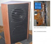
Without getting too much off topic with this, I have what's in the picture below. That's a class B, 500 watt amp that works fine. This is driven by a Linkwitz Transform (19 db boost at 20 Hz). As a future project, I want to replace that amp (my first attempt at amp building) with a better performing (nicer looking) ones.
As you say Andrew, I can use two of this amp project, one for each woofer. I could plan the PC board for extra output devices, to operate at 70 V rails. Each woofer is 8 ohms, so I'd be looking for 250 watts into each woofer to equal the current one.
I would, of course, change some of the transistors and other components involved to accomidate this higher voltage.
Attachments
- Status
- Not open for further replies.
- Home
- Amplifiers
- Solid State
- Help with this amp? A patchwork product of simulation