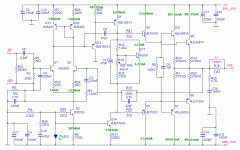
Hi,
Nice, clear Lin-toplolgy amp design, I like it!
I'm sure your design should work and perform good but I've some comments:
- I would place a resistor in series with R18 for some protection purpose, because when R18 adjusted 0 Ohm then output stage would blow because of enermous bias current and thrmal runaway. A serial resistor could solve this problem.
- R20/21 seems to be too low. For OP devices 1...3.3 Ohm is correct value but for drivers I rather use 22...220Ohm.
- R9's ground need to be the signal ground
- for 4 Ohm speakers I would change C18 to 150nF, preferably FKP
- I would fusing the rails, say 6.3A/F
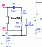
- what about placing a terminating resistor on the input terminals? 100k...220k will do the job.
- C8 Miller cap seems to me a bit high, I wolud try 68pF or even 47pF.
Cheers,
Dzsoni
Hi Dzsoni, thank you for the encouragement. 🙂
Series resistor with this pot is a good idea - I'll do it.
No problem changing R20 and R21 (I don't have these 1.2 ohm values anyway). Testing with 50 ohms.
I'll route R9 to signal gnd.
I most likely will not be using this amp for 4 ohm load.
Fuses yes. Will add after.
What do you mean "terminator resistor"? I don't know what that is.
Miller cap - I have some nice monolithic ceramic 100pF caps but no 68pF or 47pF. I will make the change on the schematic, but unless I get others, I'll use the 100pF's.
Also, my earlier offset problem at the base of the drivers can be cured by changing the forward voltage drop of LED1 from 1.66V to 1.54V. Now, I know an LED is not adjustable, but is there another way to do this?
Thanks for the help.
Hi,
About terminating resistor see attachement.
Decreases noise and using it will not allow C6 to form a low pass filter with a series resitor that is on the output on the source.
Now R2 and C6 forms the filter, but let's think about what happens when say there is a 4.7k resistor on the output of the preamp. Then R2 will be virtually 5.7k...
Most designer omits this resistor but for example John L. Hood and others are always used them (see Naim).
Cheers,
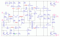
Schematic update.
I have included the improvements recommended by Dzsoni: Adding a 160K resistor to the input, a resistor in series with pot R18, increasing base stopper values on Q5 and Q6 and I have changed the miller cap to 47pF.
Also, recommended by Andrew, I have changed R19 to 3.9 ohms (forgot to do on an earlier update).
Attachments
Hi,
did any of those changes make any difference to the sim report?
How does the sim react to changes in C10's value?
Have you checked that each of the currents through all the components make sense yet?
Are all the voltages making sense?
How about increasing the LTP degen values to 100r or even 200r?
What about changing that EF to a low capacitance type, eg 2sa1360?
and adding a protection transistor (To92) around the VAS/EF?
I make r33 much larger (2M2) to ease the load on the source and make r22 larger (300r), but this is only my preference.
Stability compensation cannot properly be assessed in the sim. You will need to fine tune the final PCB values.
Hi,
I widely used 100k as terminating resistor, in my latest design I used 470k as I remember. I have never had any problem with these values. The input impedance of MJL21193's amp will be enough higher (about 30k) then the "standard" 10-20k.
But I trust AndrewT so you could use a resistor with a value somewhere between 100k and 2M2, say 500...800k
You mean R23/R24? As I know R=26/I(mA) is the right formula.
Good point, Andrew. I agree 100% here.
I widely used 100k as terminating resistor, in my latest design I used 470k as I remember. I have never had any problem with these values. The input impedance of MJL21193's amp will be enough higher (about 30k) then the "standard" 10-20k.
But I trust AndrewT so you could use a resistor with a value somewhere between 100k and 2M2, say 500...800k
How about increasing the LTP degen values to 100r or even 200r?
You mean R23/R24? As I know R=26/I(mA) is the right formula.
Stability compensation cannot properly be assessed in the sim. You will need to fine tune the final PCB values.
Good point, Andrew. I agree 100% here.
The changes had subtle results, total of all is now I'm getting .000% THD consistently. That's at 1KHz at 152W into 8 ohms. Something must be right. No other amp I've modeled has come close to this (as mentioned before, the SymaSym was the best at .008% THD at full output)
Changing the emitter resistors higher results in higher THD. 22 ohm seems to work about the best here.
I'm working on a schematic that will have current and voltage readings at different places. I'm still not 100% sure what these readings should be.
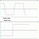
I have a couple of square wave plots to show. The one on top is at 20Hz and the one on the bottom is at 300Hz.
Any explanation for the sharp down slope at 20Hz? Still a small amount at 300.
Any ideas?
Attachments
Hi,
These square wave graphs are just normal.
These slopes are caused by the high-pass filter poles: in the input (C5-R3) and in the feedback (C3-R9).
Try the following with your sim: change C5 and C3 to a really-really big value, say 10.000uF. Then watch 20Hz and 300Hz sq-wave with the sim's scope.
You will find the slopes will disappear.
Of course in practise never use such high value caps there, these 2.2uF and 220uF are just fine.
Hi,MJL21193 said:The changes had subtle results, total of all is now I'm getting .000% THD consistently. That's at 1KHz at 152W into 8 ohms. Something must be right. No other amp I've modeled has come close to this (as mentioned before, the SymaSym was the best at .008% THD at full output)
Changing the emitter resistors higher results in higher THD. 22 ohm seems to work about the best here.
I'm working on a schematic that will have current and voltage readings at different places. I'm still not 100% sure what these readings should be.
I have a couple of square wave plots to show. The one on top is at 20Hz and the one on the bottom is at 300Hz.
Any explanation for the sharp down slope at 20Hz? Still a small amount at 300.
Any ideas?
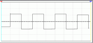
is that overshoot on the leading edge of the square wave.
Do 1kHz sqwave and zoom in to see. Indicates a lowish phase margin. Temporarily reduce r2 to 10r to remove most of the low pass filter action and see if the overshoot gets worse. Then try 10kHz sqwave.
How much does the sim say the distortion gets if you increase r23/24 to 200r? does it exceed Symasym? Does it get rid of the overshoot?
Don't trust me, I'm only a learner here too. Read more opinion and weigh up the pros and cons. Build it and assess the result. Then tell us I was wrong.Dzsoni said:But I trust AndrewT
AndrewT said:
Do 1kHz sqwave and zoom in to see. Indicates a lowish phase margin. Temporarily reduce r2 to 10r to remove most of the low pass filter action and see if the overshoot gets worse. Then try 10kHz sqwave.
How much does the sim say the distortion gets if you increase r23/24 to 200r? does it exceed Symasym? Does it get rid of the overshoot?
Plots for the 1K and 10K with R2 reduced to 10 ohm are below.
Distortion goes up to .003%, so no, not as high as SymaSym. No, still a slight overshoot on the squarewave at 1K.
Attachments
Dzsoni said:Try the following with your sim: change C5 and C3 to a really-really big value, say 10.000uF. Then watch 20Hz and 300Hz sq-wave with the sim's scope.
You will find the slopes will disappear.
Right on the money, Dzsoni! Perfectly flat.
Attachments
AndrewT said:Hi,
a big change from 1mA to 2.6mA. but I think better. Running between 2mA and 6mA is the norm although few amps run at less than this.
I meant C3 plus the capacitance of the EF.
It takes AC current from the LTP collector. So half the time it is sucking current out of the collector and the rest of the time it is injecting current into the collector. The poor mirror ignores that and keeps sending the same current out of it's collectors. I wonder if that is why so many say that an LTP loaded with a mirror does not sound nice?
That doesn’t sound right. The current mirror effectively provides push-pull current drive to the miller capacitance. This effectively DOUBLES the current available for linearly driving the miller capacitance out to HF. It is much more effective than a crappy resistive pull up and is very advantageous, as this is where probably 90% of amateurs honestly reporting bad sound from this kind of topology stuff up in regards to applying miller compensation – the LTP must have a high enough tail current to drive the miler cap at high frequencies. Stuff up here and the amplifiers HF performance can go right down the crapper.
It has not been my experience in the least and I don’t know how any consensus that I mirror loading of the LTP is generally bad for sound can be reached, other than amongst tweakers who like fudging values without a clear understanding of what they are doing.
I've never seen anyone complain about "bad sound" from a current mirror loaded diffferential VAS, which is a very popular topology too, BTW.
Cheers,
Glen
G.Kleinschmidt said:
Cheers,
Glen
Hi Glen,
In general, what do you think? Look ok or start again?
Your front end is very similar the the JE-990 which is an excellent design. You're ahead using, a current mirror and beta multiplier, I'd add a Baker clamp as seen in the 990. You might just want to take a look at this thread about the JE-990:
http://www.diyaudio.com/forums/showthread.php?s=&threadid=107404
Check to see what your design does when driven 20 - 50% into overload at 20 KHz. Like it or not you will probably hit some clipping from time to time.
I also suggest that you use andy_c's models for your output devices, the OnSemi models have problems. I noticed that you were using BD139/140 at one point, the OnSemi models also have issues, use Fairchild instead if you go back to these. They might be better for your emitter follower off the diff pair, or even better the 2N5400, check for Pdiss and max Ic though, under worst case conditions.
You probably have very high open loop gain because of the current mirror and beta multiplier this is how you're getting such low distortion. You might want to try higher emitter degeneration on the diff pair, and a bit on the VAS to improve the overload and open loop performance.
Pete B.
MJL21193 said:
Hi Glen,
In general, what do you think? Look ok or start again?
G'day. Definitely no need to start again 🙂
A few niggles though:
I’d omit C19 and R28, connecting C12 directly across the LED.
You are using a bit of a big transistor for Q14, which has high collector-base capacitance. With the high voltage signal swing at it’s collector, modulation of the bias voltage (and LTP tail current) via Cob at high frequencies could be an issue.
A nice, low ESR capacitor for C12 would in order. Maybe even another one from the base of Q3 to the negative rail. At 22k R9 is a bit large too. Drop to around 1k or so.
An alternative would be a seperate LED of Q14.
Cheers,
Glen
Did you intend to run this as a Class A amp?
You've got nearly 1 Amp through each output device. You need to reduce this to around 100 mA to have reasonable idle dissipation. Recheck your distortion, it will probably be higher.
Pete B.
You've got nearly 1 Amp through each output device. You need to reduce this to around 100 mA to have reasonable idle dissipation. Recheck your distortion, it will probably be higher.
Pete B.
- Status
- Not open for further replies.
- Home
- Amplifiers
- Solid State
- Help with this amp? A patchwork product of simulation
