Good luck. I'd appreciate an update on your progress as I've still not got mine to consistently play CDs.
I will keep you posted…Question: I noticed that after the ? appears the equipment enters the power down mode, is this normal …
Yes. When you press any button in standby mode you'll hear a click as it goes from standby to operating. The click comes from a relay on the standby board; the one by the transformer. When it errors it must think you're done with it and goes back to standby. You should hear the relay again as it disconnects the main power.
Due to flex cable on Servo board It was pretty complicated to replace capacitor C2103 it measured ~20 uF rather than 33uF.
I noticed laser is moving up-down 3 times but no light on my phone.
Rechecked the supply voltages, the -6V reads a very low -3V. At first glance suspected too much load by the Servo board. Disconnected servo -6V input to unload. Voltage at Decoder board remains a low -3V while input to IC6310 is a sufficient-14V.
Checked caps C2402 and C2344 as well as TR6328 all OK.
The regulator IC6310 measured OK when tested in circuit with VOM. Replaced the 79M06CT (IC6310) anyway as a last attempt.
The -3V is now restored to -5.85V close enough to -6V?
Reassembled the unit…..BINGO it reads TOC and plays the CD without the deadly “?”
Connected to Beomaster 3300 and there is sound. Pfffft.
The lid closes nicely without its previous bouncing after replacing the C of 68uF (measured 30 uF) by a 100uF type.
Please note the PCB shows it must be connected between ground and pin5 (motor up) of connector P43 while electrical diagram shows it as connected to pin4 (motor down)
During my trouble shooting I have found quite a few drawing errors….
Well done. I've already replaced all the voltage regulators, but it might be worth revisiting. But, I think my fault may be mechanical and not electrical. I say this because I don't understand how it can work after being put back together and then after a few days not work.
At the moment I'm struggling to get the eject mechanism to work. I took it out to replace the hinge, decided to put it back without replacing the original hinge and now the arm (the one that clips to the eject button) fouls on the hinge so it won't go down far enough to slot into the opto switch.
At the moment I'm struggling to get the eject mechanism to work. I took it out to replace the hinge, decided to put it back without replacing the original hinge and now the arm (the one that clips to the eject button) fouls on the hinge so it won't go down far enough to slot into the opto switch.
Just sorted out the opening problem. Lid was sitting too low when closed due to the rubber bits the lid sits on at the front having rotted away. Not sure why it didn't do it before I started messing with the eject mechanism. But, it did give me a chance to see how complicated it is.
On my unit the 2 rubberstops #9018 are absent, I gonna check whether a 2-3 mm shim will make a difference as even with the new belt the lid opens only ~~15mm and then needs a little assistance from my finger to go fully up. I wonder whether the disc clamping block attached at the underside of the lid #9001 is resisting the smooth opening. Another possible friction item I still have to investigate is the drive to the flapping thing by the items #9021-9022.
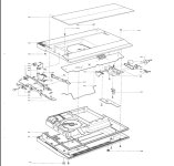
As to your intermittent failure of not reading the (same) disc, I recommend you check the solder joints and eyelet liftings on the Decoder PCB in the area’s where large components are mounted (Regulator IC, Elco, Connector).when all your supply voltages checkout OK it may help to have your unit lifted on stands from the bench so to be able to spray COLD or HEAT to the solder side of the PCB when the disc is playing correctly.
A place not to be overseen is the connection of the flex cable connected between SERVO board and LASER mech. (Its connector punches little holes in the flex circuit traces which may become corroded/damaged when frequently disconnected or stored in humid environment. I would not encourage the disassembly as it is a delicate job.
Attachments
@Brasto I need your help in understanding some power readings from the servo board. The 5 pin connector which takes the power from the decoder board
Pin 1 should be +10v; I have +12v
Pin 2 should be +5v; I have +5v
Pin 3 ground (which is ground hooray 🙂)
Pin 4 should be -6v; I have -6v
Pin 5 should be -10v; I have -13v
Do you think pin 1 & 5 are outside acceptable tolerance? I'm going to trace the circuit back to the decoder board power regulators, which I thought I'd replaced all of them, to see if I missed one.
But, good news, the laser power is reading within tolerance at about 50mv.
My manual says there is a tolerance of +/- 2V on the 10 volt output
So officially your -10v is out of spec.
Please notice that -10V is applied to opamp on the servoboard driving the focus motor, so your focus of the laser maybe not OK
There must be also a +/- 15V generated at the Decoderboard, advice to check them to be complete.
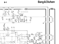
You can try to adjust R3146 iaw this procedure Please note that in the English text they want you to connect Voltmeter across 30R2136 which is an error it shall read 30C2136. But if you have never touched R3146 before I would try to get the -10V in tolerance by checking R3393 and TR6314 on the Decoderboard.
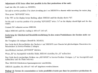

So officially your -10v is out of spec.
Please notice that -10V is applied to opamp on the servoboard driving the focus motor, so your focus of the laser maybe not OK
There must be also a +/- 15V generated at the Decoderboard, advice to check them to be complete.

You can try to adjust R3146 iaw this procedure Please note that in the English text they want you to connect Voltmeter across 30R2136 which is an error it shall read 30C2136. But if you have never touched R3146 before I would try to get the -10V in tolerance by checking R3393 and TR6314 on the Decoderboard.


Last edited:
Thanks, especially the comment about resistors and capacitors. I agree it's not right to touch the focus until I've got the correct voltage coming into the servo board.
I was clearly completely wrong about it possibly being a mechanical error with the servo power input being wrong, but I'm puzzled why due to the fact I replaced all the voltage regulators on the decoder board. Having said that, I may have put one in with a bad solder joint. Back to checking components and joints again.
I was clearly completely wrong about it possibly being a mechanical error with the servo power input being wrong, but I'm puzzled why due to the fact I replaced all the voltage regulators on the decoder board. Having said that, I may have put one in with a bad solder joint. Back to checking components and joints again.
Nick, We are now in the same boat, I grabbed the cd3300 after a week again and IT FAILS TO READ ANY CD.
So I am back to square one, …nice Xmas job
So I am back to square one, …nice Xmas job
On the one hand, I'm sorry to hear that. But, on the other, it's nice to know I'm not the only one with this problem 😉
I've been looking at the power supply to the servo board; why I'm getting +12 and -13 volts when it should be +/-10. First thing to say is that it should be +/-9.5v input on the board I have in my machine as I must have focus off-set adjustment whatever that is. So, the +12 & -13 volt input power is even more out of spec.
Next, the correct voltage does not go through any voltage regulator. I think it goes straight from the mains transformer at 25v into a set of 4 diodes, I assume making a bridge rectifier, and then takes a slightly different route depending on the final voltage required. The +10v goes through capacitor 2396 (4,700 uf 16v). The -10v goes through capacitor c2397 (1,000 uf 16v) and then TR6134. I'd already changed c2397 but not c2396. c2396 on my board looks like a metal can with 1 +ve and 3 -ve connections. But, in the board it tests fine with maybe a slightly high ESR, 0.11 ohms, depending on what table on the internet you look at.
I've tested the transformer output and get 22v, I think, as I'm not exactly sure how to test it. I took a reading at the transformer using the two 25v outputs. Using the same method the 50v output is giving about 40v.
And that is where my knowledge ends. What I don't fully understand is how the 25v is dropped down to 9.5v just using diodes and capacitors. I've read there will be a small drop across a diode, but over 3v for each diode in series to give the 15v needed?
I'm hesitant to change out all the components in the servo power route without getting a better understanding on how each one does its job. I've already changed enough components with long term success.
Oh, one thing I did find by accident. The service manual shows how to split the machine to allow testing, section 6-2 if you've got the same manual as me. I forget to reconnect plug 46 (page 2-10) to the servo board from the display board, powered it up, pressed play and the machine continued to supply power to the decoder board until I powered it down.
If this is related to your problem, I'd appreciate to know what you find.
Good luck and Merry Xmas.
Hello Nick a Happy New Year but not yet for the CD3300.
You wonder how the transformer could make the 9.5 volt, well please note the transformer secondary voltages are labelled Vpp Peak to Peak voltages alternating at 50 Hz normally to be observed using an oscilloscope. After the full wave rectifier bridge the voltage has become DC smoothed any further using the electrolytic caps C2396 or C2397. Using the formula Vrms = Vpp / (2√2) you will observe a RMS voltage close to 8.8 for the 25Vpp xfmr and close to 17Vdc for the 50Vpp winding.the smoothing caps shall bring the DC voltage close to the listed values. The fact that we are having readings of -13 and +12 Vdc indicates that sources are not loaded normally. Maybe some hated plated thru holes or cold solder joints are causing our problem…
I am using the manual with 56 pages and this first page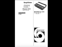
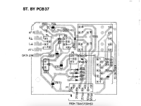
As a last resort I think about making a special support allowing me to access of PCB’ while the CD3300 is trying playing a CD🤬
You wonder how the transformer could make the 9.5 volt, well please note the transformer secondary voltages are labelled Vpp Peak to Peak voltages alternating at 50 Hz normally to be observed using an oscilloscope. After the full wave rectifier bridge the voltage has become DC smoothed any further using the electrolytic caps C2396 or C2397. Using the formula Vrms = Vpp / (2√2) you will observe a RMS voltage close to 8.8 for the 25Vpp xfmr and close to 17Vdc for the 50Vpp winding.the smoothing caps shall bring the DC voltage close to the listed values. The fact that we are having readings of -13 and +12 Vdc indicates that sources are not loaded normally. Maybe some hated plated thru holes or cold solder joints are causing our problem…
I am using the manual with 56 pages and this first page


As a last resort I think about making a special support allowing me to access of PCB’ while the CD3300 is trying playing a CD🤬
Thanks for the explanation about the transformer. I am well out of my comfort zone with transformers. I did ask the question about the +/-10v unregulated supply in the Electronic Design forum here and got this answer;
"The voltage is not reduced to 10V. The bridge rectifier is connected to 20VAC. And the DC is +10 and -10, total 20V. Since you write you measure +12V and -13V this is perfectly normal. The voltage should be (20V - 2 * 0.7 V) * 1.4. Minus some tolerances and current draw this is what you measure.
Philips calls this +/-10V but as it is unregulated it is just a signal name."
Yep that's the same service book I found.
Have you checked the voltages on the 4 regulators? I had to change the +15v 6308 with another brand new one (I'd already replaced the original some weeks ago just in case. I managed to short it out when checking voltages doh!!) and the latest was only giving 10v. I put back in the original and that still only gives 10v. All the other regulators read correctly. I know this is not related to the servo board supply, but who knows?
With regard to the bad solder joints, I think I've pretty much done them all again, including the chips and connectors. There is forum talk about dodgy vias on the decoder board. What do these look like because I can't see any that resemble what I've seen using a google search?
Good luck with the support.
There is forum talk about dodgy vias on the decoder board. What do these look like because I can't see any that resemble what I've seen using a google search?
Good luck with the support.
https://www.bramjacobse.nl/wordpress/?s=griplets
@bram jacobse Thanks. I'm pretty sure I've resoldered all the ground connections. But, may well have missed some of the griplets.
First thing I did put it in my testrig in vertcal position allowing me to play and touch the pcb’s at the same time. This was my test rig a simple vice with some foam padding:
I used a wooden stick to poke the circuitry and when I touched the flex it came alive.

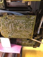
Obviously there was some glitch with the flex print cable going from P31 on the servoboard to the moving laser unit.
I have removed the flex at the P31 connector and cleaned the pitted contacts thoroughly. Job done. It plays CD’s all OK, will leave it at rest for a couple of days and try again…
- Home
- Source & Line
- Digital Source
- Help with CDM2/10 mechanism in a Bang & Olufsen Beogram CD3300
