A reminder when I had the flex reinstalled it appeared the laser assy could not move freely and was sticking due to the flex hitting some bracket. Be very carefull when working this area
@Brasto many thanks for the update.
Whilst it doesn't appear to be a mechanical problem per se, I did think that, as it worked for a short time after reassembly it might be the rubber mounts, so I took the CD module out the other day and put it straight back in but got no joy. I didn't disconnect the ribbon cable. If it is the ribbon cable, I wonder if it comes loose from its servo board connector because I didn't push it in far enough, or as you say it has some dirt buried in the connector or on the connects. Before I do anything I'll wait for you to say if it still works after a couple of days.
If that does solve the drive/reading CD problem, I then need to see if the 15v voltage regulator giving 10v is an issue. Hopefully not.
PS - Love your test jig.
Nick I tried my CD3300 this weekend. The result? It played my CD’s so I guess problem solved, faulty flex connection in the servo board
Excellent news. I took mine apart yesterday, and funny enough the ribbon cable just fell out of the board connector. I'll put it all back together tomorrow, after cleaning the cable contacts, and let you know what happens.
That maybe a clue, but normally the connector should not release the flat cable unless the lock is lifted. Recommend you use a magnifier glass to carefully inspect the pitted indents on the flat cable. When unreliable you can use scissors to cut the flat e.g. 1 mm shorter. About the 15/10 Volt issue, did you check or replace the diode D6353?
Attachments
Yes, I should have said I realised my cable clearly wasn't connected properly. I haven't looked at the voltage issue yet. I'm going to put it back together today, after making sure the ribbon cable looks OK, and see what happens. Please correct me, but I think the voltage issue relates to the decoding side of the operation and shouldn't affect the CD reading. No sound maybe, but that's a problem for another day 🙂
Cleaned the connectors with IPA, put it all back together with cable definitely firmly plugged in this time. Made absolutely no difference. I'll take it apart again, and this time use very light sand paper to clean the contacts. I'm a bit reluctant to trim back the cable to above the pitting as it's a few mm up and I'm worried too much will need to be taken off for it to make a good contact.
Cleaned it all, put it back together again and then checked each servo board connector pin to the laser assembly. They are all connected, or at least they show no resistance with the meter.
My conclusion, doesn't appear to be the ribbon cable.
My conclusion, doesn't appear to be the ribbon cable.
It is a stubborn piece of crab. You said earlier laser current is correct. I would try to run the checkprocedures in the manual at para 7-1 and 7-2, maybe it will tell you where the problem is hiding..
Ok, I give up.
I identified the source of the funny +10v output from the +15v regulator. Me!!! I brilliantly replaced the +15v 78M15CT with a -15v 79M15CT. Note to self, remember to take glasses off when trying to read small print on components. Doh!! Changed the component and voltages are as they should be. Put it all back together, AGAIN, and it still doesn't work.
I seem to be back to where I was a few attempts ago. Instead of failing instantly, the disc now spins for a few seconds before failing. Having said that, on one occasion it did read a 70 minute CD as lasting only 38 minutes. But, it then crashed when I tried to play the CD. But, only once did it do this.
I suppose I could revisit the ribbon cable again and this time carefully cut off the bit below the connector indentation marks to make sure it's a virgin piece of cable. But, that does run the risk of cutting it too short. And, as I've managed to butcher several solder pads on the 40 year boards (changing the regulator again comes to mind as the solder pads just disappeared), I'm more than a little hesitant to try this.
My gut feeling is I've blundered around and caused more issues than were there originally. I then repair one of my errors and cause another. I suppose using a 40 year old B&O CD player as my introduction to electronic repairs was a little optimistic.
When I get the motivation back, I'll try the diagnostics function but for now I'm just going to leave it where it is and glare at it each time I go past. Maybe I'll shame it into working.
Nick, no need to blame yourself the markings on semiconductors with an 8 or 9 are candidates for errors…
Before giving it all up spent a few minutes to run the para 7-1 and 7-2 tests
Before giving it all up spent a few minutes to run the para 7-1 and 7-2 tests
Completed service mode test and got as far as this;

Looks like another Google to see what all that means. The test won't go past that. If I try the next step it just ignores the >> key press. I can start the test again by pressing Advance but it always stops with an F4 error.
Looks like another Google to see what all that means. The test won't go past that. If I try the next step it just ignores the >> key press. I can start the test again by pressing Advance but it always stops with an F4 error.
Nick je bent op de goede weg. Jouw CD3300 blijft dus hangen op F4, dat betekent dat de radiaal servo een probleem heeft.
Ik zou alle voedingspanningen op het IC 6102 op het Servoboard eens gaan meten.(ik hoop dat je een goed testprobe hebt zodat je geen sluiting zult maken). Ik weet niet of je de beschikking hebt over een oscilloscope, maar de hi-low testen volgens para 7-7 kan je met een multimeter uitvoeren.
Ik zou alle voedingspanningen op het IC 6102 op het Servoboard eens gaan meten.(ik hoop dat je een goed testprobe hebt zodat je geen sluiting zult maken). Ik weet niet of je de beschikking hebt over een oscilloscope, maar de hi-low testen volgens para 7-7 kan je met een multimeter uitvoeren.
Attachments
Nick I found a listing made by a friendly russian detailig the application of various CD player components by manufacturer:
https://vasiltech.narod.ru/CD-Player-DAC-Transport.htm
It shows that B&O CD3300 has the Philips CDM-2/10 installed
The service manual for this part gives a lot of details that may help you
The file size is not allowed here, check the www for philips cdm-2 servicemanual
https://vasiltech.narod.ru/CD-Player-DAC-Transport.htm
It shows that B&O CD3300 has the Philips CDM-2/10 installed
The service manual for this part gives a lot of details that may help you
The file size is not allowed here, check the www for philips cdm-2 servicemanual
Thanks @Brasto for this information and your previous post. As it happens I already have a copy of the CDM2/10 service manual.
Before I start looking at another electronics problem, I'm going to take the mechanism apart. I found this link from diyAudio that mentions the bearings getting stiff and causing the error message.
I have taken it apart in the past and wonder if a) I was a little off when I reassembled it or b) it needs a little more, or less, lubrication.
Before I start looking at another electronics problem, I'm going to take the mechanism apart. I found this link from diyAudio that mentions the bearings getting stiff and causing the error message.
Hello all,
I'm trying to fix (and understand!) my long served and well beloved 1988 vintage Philips CD350 player, which uses a CDM-2 drive.
The problem is a severe difficulty in acquiring lock of the radial servo. It makes horrible noises while it struggles to read the TOC, and most of the time it fails and gives up. It's a bit worse with some disks than with others. IF the player manages to acquire radial servo lock, it then easily reads the TOC and plays the disk without any further trouble.
It's sensitive to the position of the player. Placing it on an inclined surface seems to...
- ludens
- Replies: 5
- Forum: Digital Source
I have taken it apart in the past and wonder if a) I was a little off when I reassembled it or b) it needs a little more, or less, lubrication.
Well Nick see the friction and lubrication of the bearing as a last resort…did you try to have the player tilted in all axis or do you feel any friction to the laser arm when moving it by hand?. Does it always return neatly to aprox center position?
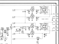
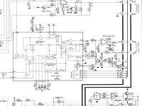
I've taken readings from the IC6102 pins, as in the photo. Readings are Volts unless specifid as microvolts
 Supply at pins 6 and 11 seems to be OK.
I also took readings at connector 31 and got these
Pin 1 -5.8v should be -6Va
Pin 2 4.9 HF
Pin 3 -4.6 D4 (buzz)
Pin 4 -4.6 D3 (buzz)
Pin 5 -4.6 D1 (buzz)
Pin 6 -4.6 D2 (buzz)
Pin 7 1mv Ground connection so I assume background mv
Pin 8 1mv LM
Pin 9 1.3mv LO
Pin 10 1.2mv Ground connection so I assume background mv
Pin 11 1v +radial motor
Pin 12 .2v -ve
Pin 13-0.6v -ve focus motor)
Pin 14 0.3mv +ve
Where it says buzz, I found there was a noise from the mechanism as I put the +ve meter probe on the connector solder point.
As I don't have a scope, I think I have done all the tests I can.
I said I was going to check the lubrication of the bearing but thinking about it, the laser assembly seems to move freely so I'm not sure I'll achieve anything by taking it apart again,
Any suggestions based on the above will be greatly appreciated.
Hi Nick you have measured the voltages on the servo board and I could not see any abnormalities. Let us focus now on your test results of chapter 7-1 and 7-2 It hangs on step 4 which means the tracking correction circuit does not function correctly, the RE Radial Error is somewhere at fault. Previous successful test indicated that the laser arm moved correctly and freely over the full range of travel from completely in to out.
The failing step 4 is the fase where laser arm is trying to center around the tracks in it’s preparation to read the TOC (Table Of Contents) of the disc. The arm should be very close to the spindle motor (fully in).
You measured at P31 pin 11: 1V and pin 12: 200mV. It would be interesting to know where the arm is located while the disc is rotating in step 4 while you hook up your meter across pin 11 and 12 (not to ground). See whether this voltage fluctuates when you lightly tap on the cabinet.
Not having an oscilloscope I recommend to go to para 7-3 and measure the status hi or lo on IC 6301 (We are now on the Servo Panel para 2-5) follow the steps as given and note any different in status when switching between steps 3 and 4 of the para 7-2. Please note that 5 V power from the Decoder board is also applied to IC6301
The Service Manual dor the CDM-2 explains in greater detail the RE Radial Error correction in para 3-6 or 3-10.
Nick when everything fails suggest to find a working CD player containing the CDM2 as a donor.
Hi @Brasto
Thanks for such a detailed answer. I really appreciate the time you're spending on this.
When doing the stage 4 test the arm is fully to the centre.
What's still puzzling me is how, on three occasions, it's worked for a few days and then stopped. If it was an electronic component issue, why fail and then start again? In your case it was the ribbon cable (I assume yours is still working).
I think I'll follow your suggestions first as I can do those without taking the CDM out again. Then, take out the CDM and closely check the ribbon cable radial connections for any small signs of damage.
The arm should NOT be in the center during step 4 test. I guess it should be at the beginning (close to the disc motor spindle as it will be trying to read the Table Of Content (nr of tracks, time and duration)
Did the arm visually move through its extremes in the previous steps (fully IN and OUT when pressing >> and << ?
Did the arm visually move through its extremes in the previous steps (fully IN and OUT when pressing >> and << ?
- Home
- Source & Line
- Digital Source
- Help with CDM2/10 mechanism in a Bang & Olufsen Beogram CD3300