Yes, in the new schematic it´s 180pF, both. C6, C7If you increase that C the self-oscillations will disappear
Yes, This is how is mounted.This should work, but they must be very close to the gates. Several cm of track or wire to the stopper is enough to turn the lateral into a radio transmitter
I seet, but I would like to get my design working before trying a new designThe source connection of the MOSFET needs protection from capacitive loads. The small inductance of a wire-wound resistor as shown can provide this, a 0R22 value will do more than 0R1 in that regard. The gate stopper resistors will do better if there is a low pass filter capacitor between the gate and the source. The gate stopper resistors could be increased in value up to 330R and the capacitor value introduced between gate and source, decided by trial and error. This circuit looks tidier for stability as there is only one capacitor around Q4 however the value might need to be changed. This could be connected from the collector of Q4 to the base of Q2 as has been indicated in another input suggestion. I would not recommend a lead capacitor in parallel with the feedback resistor as any hf instability due to the load will be introduced to the system

Check the
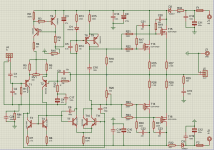
Revisiting lateral MOSFET stability
The ceramic insulators work because internal reactances no longer couple capacitively to the heat sink. The gate to drain capacitors enhance the gate stoppers because they bypass internal reactances. Also, bypass all drain connections to a heavy ground conductor with .47 uF or larger film cap. There are some disagreements in the replies, but at the end of the day, this is working in production amplifiers for us.Thanks, but my question is about post #49, in which I use Exicon ECF Mosfet, TO3Try 470 ohm gate stopper on the 2SJ162 and 680 ohm on the 2SK1058.
"Transistorlegacy,
Check theThe ceramic insulators work because internal reactances no longer couple capacitively to the heat sink. The gate to drain capacitors enhance the gate stoppers because they bypass internal reactances. Also, bypass all drain connections to a heavy ground conductor with .47 uF or larger film cap. There are some disagreements in the replies, but at the end of the day, this is working in production amplifiers for us."
I have read the link, in this case, I understand that this is for plastic Exicom Mosfet, and in my case I use Exicon Mosfet with TO3 metal encapsulation.
Sorry, I realized that in the schematic I put D2 wrong, so I think, ¿It is the same as you tell me?D3 is backwards, C4 should be Nichicon UES bipolar type - 220 to 470 uf / 25/35 volts - bigger uf is better and higher voltage is better
Attachments
YesExicon MOSFETs have the same capacitances as the older Hitachi parts. See data sheet.
I have seen this, but, because most of the schemes with HITACHI mosfet, have gate stop resistor of the same value? I have only seen it in Exicon, have a different value. And, in this case 470 and 680, could it reduce the slew rate?
Also, different values produce different Bias measurements on the source resistors, as I said, how does this affect?
Thank so much.
- Home
- Amplifiers
- Solid State
- Help with an oscillating amplifier with Exicon mosFET ECF10P20 & ECF10N20