Not really sure how to get the tube diameter smaller.
What about cutting the port short enough to still fit a cap on it, then adding some better ports to the back panel. I could just seal the cabinet but sealed bass has never quite sounded right to me.
Curious what atc does to mitigate some of these problems. their ports appear close to walls, but much further from the back wall as their cabinet depth is much greater.
You're doing great and delving into what doesn't work in a design is difficult for technical, personal, and practical purposes. We may all learn a thing or two once you're done learning a thing or two.Please be kind
EDIT: Have you managed a 4pi space measurement? (Outdoor, preferably elevated, or specifically a ground-plane measurement in a grassy field)

For testing I just partially close the exterior port end with toy putty.Not really sure how to get the tube diameter smaller.
As far as i know the effective port surface is the smallest one along the port. So it might be ok to just put a reduction cap on the inside and/or the outside end of the port.
I have a lovely outdoor area to use, but we live next to a highway. It can be pretty tough to get good measurements. Anything related to waterfall or time, forget it. I did want to develop a passive xover for these at some point, as active is quite cumbersome and doesn't agree with my income. My current setup doesn't allow me to use my audio interface inputs. I write a lot of music so not being able to toss in inputs has been killing me.
I could try a reduction to the port end on the inside, but I don't see a way of doing that on the outside that looks remotely passable.
I'm curious about the comments on the port velocity. When I ran winisd sim it told me I could get around 100w while keeping velocity below 17-18. I assume I did something wrong? I don't really hear any port chuffing even at very high volumes, and these things do get really loud.
I sort of feel like I'm approaching the cost/work ratio where a rebuild would satisfy me more. There are also other issues with these speakers that I feel could have been done better. It's getting exhausting removing bolts and trying one thing, measuring and repeating, I guess it beats wearing out the driver screws wood threadings.
Gotta go return my pvc bends as they don't fit my pipe, and that's how I learned about pvc pipe scheduling.
Last edited:
If you're not hearing much of a problem, maybe it's not much of a problem?honestly not really hearing much of a problem lately since dialing in the woofer xover more
Most every commercial speaker has measurable anomalies that in theory could be corrected. If they can't be heard, why would they fix them though? There's only so much time, money, and care to spread around.
Every speaker is inherently a long series of compromises. Figuring out which ones are worth worrying about for you/your application can help make the process more pleasant and productive.
Just a possibility ...but I don't see a way of doing that on the outside that looks remotely passable.
Attachments
Doesn't look like black magic or anything. Not sure if port is PVC, thoughCurious what atc does to mitigate some of these problems. their ports appear close to walls, but much further from the back wall as their cabinet depth is much greater.
Subjective impressions tell me the speaker without the rubber sounds better, but who knows how accurate of an assessment that is.
I'm going to hold off on anything else and take the speakers outside and try to get some good measurements to implement a crossover I know is getting me neutral results. Dialing in by ear in the room isn't paying off (wow whoda thunk) and I feel partially contributing to my problem.
I'm going to hold off on anything else and take the speakers outside and try to get some good measurements to implement a crossover I know is getting me neutral results. Dialing in by ear in the room isn't paying off (wow whoda thunk) and I feel partially contributing to my problem.
Well I measured the woofer and mid outside and came up with some good 4th order filters, I can still just hear something off with the port and bass.
I know speakers are compromise but I don't think anyone would be happy with what I'm hearing, really calls attention to itself. I've reached the point where I no longer want to troubleshoot this and would like to start over. I'm not sure how to avoid the same problems but I may make a new build thread and hope others can help sort out something better. I am thinking a separate bass cabinet that will save my back and allow flexibility with bookshelves.
I know speakers are compromise but I don't think anyone would be happy with what I'm hearing, really calls attention to itself. I've reached the point where I no longer want to troubleshoot this and would like to start over. I'm not sure how to avoid the same problems but I may make a new build thread and hope others can help sort out something better. I am thinking a separate bass cabinet that will save my back and allow flexibility with bookshelves.
~13543/2/10 = ~677 Hz (344 m/s, 0.254 m using this 'open cylinder' calculator)
No clue what happened to the link as it worked when I checked it right after posting 🙁 Oh well, 'stuff happens': http://hyperphysics.phy-astr.gsu.edu/hbase/Waves/opecol.html#c1
Well actually, it may be too early or abandon this cabinet. I did one last ditch effort measuring the speaker outside to see how my current filters respond to the raw driver response, while not as smooth as I'd like, look at the woofer. It has elevated response above 100hz that a simple low pass wouldn't work with. I believe this is the cause of my troubles. What do you think?

Hmm, not too sure how accurate that is. Speaker was about 5 feet off the ground, pretty much nothing around but some tree's, mic 1m away at tweeter height. When I tossed the pit viper crossover on it, vcad gives me much different results than what the speaker actually measured with the passive network. Not sure what to make of this.
I suggest you track down a 'prefabricated' adjustable port of a size to fit inside your current port (with a bit of 'thin foam wrap' to fit it).Not really sure how to get the tube diameter smaller.
With a bit of luck, you will find a front flange just wide enough to mate with your 4 inch tube. (perhaps along with a little putty/silicon art-work)
The problem is obvious; I had similar one.
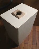
Your cabinet is quite tall, so a standing wave forms in a woofer operating range. Appr. 160 Hz resonance corresponds to ~1.1 meter half-wavelength, which seems to be the vertical dimension of your enclosure. Pressure maxima are near the boundaries, i.e. cabinet walls, right where you placed the bass port, where standing wave influence is as strong as it can be. The solution is to move the port to the middle of back panel, where vertical standing wave have a pressure minimum.
Another, more complicated option is to add tuned Helmholtz absorber inside the cabitet at the top boundary. By doing so in one of my designs I was able to kill two first modes of a tall cabinet with a set of tuned absorbers. My cabinet was slightly lower, so it resonated at 180-190 Hz instead of 160, but underlying principle is the same.
this might be the project that gets me out of diy and onto some pre-built monitors. so discouraging. prob pull the drivers to sell and let mold eat the cabinets in the garage. thanks for the help everyone.
Hi, yeah it is a lot of work to weed out issues and is aburden unless one really enjoys the whole (most) of the process 🙂
It is nice you've realized what is your priority! I wish you nice time with audio hobby, and life in general! 🙂
It is nice you've realized what is your priority! I wish you nice time with audio hobby, and life in general! 🙂
Don't lose your heart. It's normal to run into problems like this, and to improve your skills and character by overcoming them. You have built a beatiful cabinet and had a good sense to make a detachable baffle, so no modification is out of your reach.


It really takes a special effort to tackle box and surround resonances. Most audio companies don't care.
As a stopgap solution you can cross sd315a and dc130 at 100-150 Hz, so the longitudal cabinet mode (mostly) won't be excited by the LF driver.
If only they didn't suffer from the same problems. The esteemed JBL M2 have tons of resonances in the midrange and kinda subpar cabinets. Original ATCs resonate too.some pre-built monitors
It really takes a special effort to tackle box and surround resonances. Most audio companies don't care.
As a stopgap solution you can cross sd315a and dc130 at 100-150 Hz, so the longitudal cabinet mode (mostly) won't be excited by the LF driver.
My 8030c's didn't have this problem, too bad I'm an idiot and I thought I could do better and sold them. My original plan was to build a bass module for them, but my brain saw ATC stuff and let the visuals and brands reputation convince me I could make something similar. Lol I don't even have the mid dome.
I love the build process, but the trouble shooting and being you're own QC drive me nuts. Testing things to fix this is exhausting.
Hi, yeah it is a lot of work to weed out issues and is aburden unless one really enjoys the whole (most) of the process 🙂
It is nice you've realized what is your priority! I wish you nice time with audio hobby, and life in general! 🙂
I love the build process, but the trouble shooting and being you're own QC drive me nuts. Testing things to fix this is exhausting.
I think you built great looking cabs and if you were to redo the baffles, maybe centered drivers + shorter dual ports half-ish way up would be another option (like Spendor Classic 1/2, 100; also Harbeth M40)


Reflex has 2 peaks. First peak defined by volume of the box , and any cabinet leakage issues will cause a drop in that peak.
Second Lower Notch is port. Same thing any leakage issues will be shown by a drop in that impedance.
Looking at the lower peak. It is very low around 15 ohms

This seems to be another impedance measurement after you wrapped the port with Rubber.
Impedance for lower peak went from 15 ohms up to 22 ohms. 7 ohms difference
Extended models for T/S use 100 for no loss port and 0 be full loss.
Equivalent model shows almost Qp of 8 to match what you have, and to get up to 22 ohms would be roughly Qp of 15 to 16
So pretty big change occurred. And with round tube efficiency usually very good around 60 to 80 in a model.
Cabinet Q changed by 2 ohms. So that is a jump but smaller jump.
first measurement shows a lot of Port loss
Second measurement seems more " normal" compared to models at cabinet leakage at 7 to be around 28 ohms
So to match your first impedance peak in a model, leakage would need to be very low at 3 or 4 when 7 is about normal
I would say port is experiencing extreme losses, and overall cabinet is experiencing losses as well.
Aside from vibrational losses would look at actual gaskets just in case.
Seems if you can feel or hear the actual port rattling or vibrating and the cabinet vibrating.
that is where most the losses are happening.
So add braces, and add a few supports under the port so it dont vibrate.
actually the cabinet looks ok and was planned pretty well.
Matter of bad luck.
Ive built ports with PVC pipe and worked ok.
Actually first try was a disaster. I wouldn't be too discouraged.
Actually after you wrapped the port it seems like a pretty normal curve.
Looks like a reflex with somewhat low tuning and overall leakage of 3 or 4
when it should be around 7
Basic Bracing, and add glue / supports to the port
The large basket ring for daytons makes them mount easy.
They do need more bolt holes and check gaskets

Second Lower Notch is port. Same thing any leakage issues will be shown by a drop in that impedance.
Looking at the lower peak. It is very low around 15 ohms
This seems to be another impedance measurement after you wrapped the port with Rubber.
Impedance for lower peak went from 15 ohms up to 22 ohms. 7 ohms difference
Extended models for T/S use 100 for no loss port and 0 be full loss.
Equivalent model shows almost Qp of 8 to match what you have, and to get up to 22 ohms would be roughly Qp of 15 to 16
So pretty big change occurred. And with round tube efficiency usually very good around 60 to 80 in a model.
Cabinet Q changed by 2 ohms. So that is a jump but smaller jump.
first measurement shows a lot of Port loss
Second measurement seems more " normal" compared to models at cabinet leakage at 7 to be around 28 ohms
So to match your first impedance peak in a model, leakage would need to be very low at 3 or 4 when 7 is about normal
I would say port is experiencing extreme losses, and overall cabinet is experiencing losses as well.
Aside from vibrational losses would look at actual gaskets just in case.
Seems if you can feel or hear the actual port rattling or vibrating and the cabinet vibrating.
that is where most the losses are happening.
So add braces, and add a few supports under the port so it dont vibrate.
actually the cabinet looks ok and was planned pretty well.
Matter of bad luck.
Ive built ports with PVC pipe and worked ok.
Actually first try was a disaster. I wouldn't be too discouraged.
Actually after you wrapped the port it seems like a pretty normal curve.
Looks like a reflex with somewhat low tuning and overall leakage of 3 or 4
when it should be around 7
Basic Bracing, and add glue / supports to the port
The large basket ring for daytons makes them mount easy.
They do need more bolt holes and check gaskets
Last edited:
- Home
- Loudspeakers
- Multi-Way
- Help with 3 way