Have y'all been really impressed by your volume pot replacements? I put the alps blue velvet pot in after I did the rest of the 'stealth' mod. I didn't notice much of a difference.
The difference was smaller than the switch to RCA connecters and the nice interconnects that allowed. To my ear, anyway.
A
The difference was smaller than the switch to RCA connecters and the nice interconnects that allowed. To my ear, anyway.
A
AdamThorne said:Have y'all been really impressed by your volume pot replacements?
To my mind, you find out why you spent on a quality pot after several months, when it (hopefully) doesn't make funny noises when you adjust the knob. 😉
Hello, lost-cause.
I remember reading a post about a t-amp built into a playstation... Unfortunately I cannot find it anymore :-(
Was that your project? As I am about to try the same, I would appreciate some hints, lessons learned and pictures if you have. Thanks a lot.
I remember reading a post about a t-amp built into a playstation... Unfortunately I cannot find it anymore :-(
Was that your project? As I am about to try the same, I would appreciate some hints, lessons learned and pictures if you have. Thanks a lot.
Hold onto your hat for a few days and it will be complete.... just doing the IR reciever.......
AdamThorne said:Have y'all been really impressed by your volume pot replacements?
It has to do with detail, or lack there of. Bad pots eat a lot of detail. Good ones eat less.
Also, as stated above, the good ones tend to stay good for longer.
Lostcause said:Hold onto your hat for a few days and it will be complete.... just doing the IR reciever.......
Working on a PS-1, I am sure you have visited www.dogbreath.de ;-)
BTW: I am using the AV-out and have no plans to modify my Playstation (unless I need to move the power supply out to make room for the t-amp.
Looking forward to your "T-Station" ;-)
hi, just a noob question:
do i have to use bipolar caps or is it possible to use this one as well?:
mundorf mcap
i'm tryin' mod 3.
do i have to use bipolar caps or is it possible to use this one as well?:
mundorf mcap
i'm tryin' mod 3.
M Cap
You do not need to use an electrolytic capacitor for mod 3. The cap you have selected will do just fine. Try to use a capacitor in the 2 to 3 MFD range. This will minimize the turn on thump that comes from larger capacitor values.
The capacitor in the mod 3 illustration is an electrolytic and not a bipolar capacitor. The electrolytic capacitor has a (+) and a (-) connection. A bipolar capacitor is usually made by connecting two electrolytic capacitors together with like poles (+ or -) connected together. The allows you to use the capacitor without worrying about polarity. Manufacturers sell the bipolar capacitor in a single component. However, you could make your own, but you would need a little more than newbie knowledge. Not that it is that difficult to do.
The bipolar cap is often found in speaker crossover circuits. Although, the bipolar caps are used in various applications above and beyond speaker crossovers.
For the sake of your modification consider the M-Cap to be a bipolar. In that it doesn't really matter which end is connected into the circuit. Although, you may find connecting one end yields superior sonics over connecting the cap the other way. Check the manufactures data sheet or technical sheet.
I hope this helps.
Hi guys, I am new around here 😉
I have been reading on the mods that are posted in this thread, and I must thank Audio1st and a few others as well for sharing info regarding the sonic T-amp and the tripath 2024 chip.
After wanting to do a modified T-amp since they came out, I finally went ahead and did just that. Its a nice little amp, I see what you guys have been talking about 😉 I decided to make one for my ET-490 electronics project class, to go along with some bookshelf computer speakers I had made back in January. I also added an integrated iPod docking station.
Anyway, I just thought I would share, and thanks again for the pointers 🙂
Here are some pics: http://ebaudio.com/PA-1
(crappy cellphone pic preview, the rest of the pics are better, but bigger)
Thx 4 your help!
The amp works now really fine.
Im using it for my PC speakers.
More pics here.
The amp works now really fine.
Im using it for my PC speakers.
More pics here.
An externally hosted image should be here but it was not working when we last tested it.
An externally hosted image should be here but it was not working when we last tested it.
Hmmm. I'm beginning to think about running an active sub to take a bit of stress off the t-amp (and speakers). If I put something together with something like the BASH sub amps from Parts Express can I get output for it from just after the volume pot on my modified Sonic Impact? Or will I need a buffer?
Thx!
Thx!
Lostcause said:Hold onto your hat for a few days and it will be complete.... just doing the IR reciever.......
OK so it took at little longer to complete my 6th T-amp.....
Combi
Big shout for Pano😎
I just got myself a t-amp and wanted to try some mod. The instruction here is quite clear though I have a couple of questions that I hope someone can help me with.
What does bridge a capacitor mean. Instruction said I need to brige C3 and C4 and I have no idea what that means.
Also, how do I replace existing smd caps and replace them with bigger/better caps. I am used to "see through hole" or "point to point" soldering where I can see the 2 ends of the cap. With SMD - after I remove the existing caps, will I see the 2 ends as well.
Lastly, which mods yeild most improve in sound. I am not good at these things so to start out I only want to mod as little as possible as I am affraid I may ruin the thing.
Thanks in advance.
The term means to remove the SMD capacitor and to replace it with a piece of wire to "bridge the connection. This allows you to mount the missing device off the board in this instance. There is no need to try to mount a SMD capacitor in its place if a "bridge" is implemented.
A piece of wire like that on the end of a resistor is soldered in place of C3 and C4. Thus, allowing the cap to be wired off the board.
The upgrading (replacement) of the input capacitors yielded the greatest enhancement to my ears.
A piece of wire like that on the end of a resistor is soldered in place of C3 and C4. Thus, allowing the cap to be wired off the board.
The upgrading (replacement) of the input capacitors yielded the greatest enhancement to my ears.
Having done a few of these, I got best results with a small single strand of pre-tinned wire taken from a piece of approx. 18 gauge wire. Leave it an inch/3 cm long. Place one end right where one end of the capacitor is soldered to the board and hold it down with an alligator clip, tape or something. A hot soldering iron with a little solder on it applied to the spot will make the join very quickly. Then bend the tiny wire around the cap, trim the end, and repeat.
I found the greatest improvement with replacing the input cap, but I also got a noticeable and worthwhile improvement in bass by replacing the main power reservoir capacitor with a better grade and higher value, which is a pretty easy project.
--Buckapound
I found the greatest improvement with replacing the input cap, but I also got a noticeable and worthwhile improvement in bass by replacing the main power reservoir capacitor with a better grade and higher value, which is a pretty easy project.
--Buckapound
AdamThorne said:can I get output for it from just after the volume pot on my modified Sonic Impact? Or will I need a buffer?
Buffer = Better. But it can work without.
Just remember that what ever is tied to that line going to the sub amp - connectors, cables, sub amp input circuits and impedances, will all be tied directly to the signal you are going to amplify. That may not sound so good. But it won't hurt to try.
"Buffer = Better. But it can work without."
thx, Pano. I was beginning to figure no one would have thoughts on this matter for me. Still in the planning stage for this project, I'll have to look for some buffer implementation info.
"Just remember that what ever is tied to that line going to the sub amp - connectors, cables, sub amp input circuits and impedances, will all be tied directly to the signal you are going to amplify. That may not sound so good. But it won't hurt to try."
Huh? Are you warning me that the post-crossover line-lvl output of the sub will bypass the input filter of the t-amp? Perhaps a better play would be to remove the Pot from the t-amp and set the T up as a amp, and set the pot as a passive / buffered pre so that I can keep the pre-out / main-in (sub) loop outside of the t-amp's circuitry...
Still thinking...

AdamThorne said:Are you warning me that the post-crossover line-lvl output of the sub will bypass the input filter of the t-amp?
No, sorry - didn't mean that.
What I'm saying is - imagine this:
You take care to use the best stuff, wires, connectors, parts, amp. Then, right at the last, where the signal goes into the T-Amp, you solder in a bunch of extra stuff. Some long wires, some caps, random resistors. Do you think it would affect the sound? 🙂
Not to mention that you will be driving the sub amp from a rather high impedance source, the volume pot. Not too good for the bass.
Will it work? Sure! Will it work as well as you would like? Doubt it. As you stated, the best solution is to drive both the T-Amp and the sub amp from an active preamp. Buy one or make one, there's not much to it.
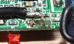
I have a problem.. I thought i was a good idea to attach the new input cap's directly to the bridged space of the old cap's. Doing this I broke of the r80 resistor on the new revision board. Can i replace this? I guess, if this is possible, i have to replace 2 resistors but where is the other one and what value do they have?
Thanx
Thanx
Attachments
- Status
- Not open for further replies.
- Home
- Amplifiers
- Class D
- Help Wiring a Replacement Potentiometer for Sonic T