Thanks for the photos, the board does look better.
Are you sure those are fuses? Might they not be Ferrites for RF noise suppression?
Are you sure those are fuses? Might they not be Ferrites for RF noise suppression?
Better board? One can hope...
Did a bit of measuring -
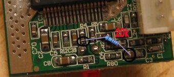
R02 measures at 10k ohms
R3 at 9.775k ohms
From C4 to R02 = .5 ohm
C3 to R3 = .4 ohm
I took the big silver slab on the left to be ground. Assuming that's the case then R02 and R3 both measure .2 ohm to ground.
This with the schematic from the first mod pano's site (just found that one recently =P) seems to make sense. Is this enough to verify Audio1st's R3 = R01 call?
Also, would anyone care to explain why the stealth mod removes these resistors, whereas "just the caps" does not? Er, if the scope of such a question isn't too large, that is.
Thx for your help, all!
Did a bit of measuring -
R02 measures at 10k ohms
R3 at 9.775k ohms
From C4 to R02 = .5 ohm
C3 to R3 = .4 ohm
I took the big silver slab on the left to be ground. Assuming that's the case then R02 and R3 both measure .2 ohm to ground.
This with the schematic from the first mod pano's site (just found that one recently =P) seems to make sense. Is this enough to verify Audio1st's R3 = R01 call?
Also, would anyone care to explain why the stealth mod removes these resistors, whereas "just the caps" does not? Er, if the scope of such a question isn't too large, that is.
Thx for your help, all!
Thanx go out to you audio1st for the new board desciption. Im going to try the stealth mod on my newboarded t-amp now. will be posting as soon as im done...
cheers! /s
cheers! /s
Ive just finished the stealth modd on my new t-amp, works like a charm, (only some rca-related problems 🙄 )
(my soldering skills have also multiplied by a handfull of infinites)
/s
(my soldering skills have also multiplied by a handfull of infinites)
/s
s_h said:Ive just finished the stealth modd on my new t-amp, works like a charm, (only some rca-related problems 🙄 )
(my soldering skills have also multiplied by a handfull of infinites)
/s
Very pleased to hear that.....
🙂 🙂 🙂 🙂
Excellent! I should have the opportunity to do the same tonight after work (I'm at GMT - 6h).
Was the sonic improvement what you have been led to expect, s_h? Do capacitors need time to 'break in'?
I also had some RCA difficulties - I figured I could just solder onto the pins on the under side of the existing input jack, but I got very noisy and almost completely attenuated signal in both channels doing that, so the next attempt will be to splice into the potentiometer feed.
Once I get all that working it'll be time to order up a good replacement pot and then maybe a new case...
At last I found a site where I can really see how these modifications are really done, great job guys.
As I am complete novice in these area (well, am a cow doctor )🙂 what is the possibility or is it possible at all to make dual-mono amp with two t-amps...would there be any benefits to the sound.
Thanks
As I am complete novice in these area (well, am a cow doctor )🙂 what is the possibility or is it possible at all to make dual-mono amp with two t-amps...would there be any benefits to the sound.
Thanks
As I am complete novice in these area (well, am a cow doctor)
Haha!
is it possible at all to make dual-mono amp with two t-amps
Many have wished to make a 2 channel T-amp into a more powerful 1 channel t-amp. Sadly, this is not possible. If, however, you have speakers that can be bi-wired then you could use 2 amps (4 channels) to run them.
In other news, I have also successfully implemented the 'stealth' mod on my t-amp. Many thanks to Audio1st for spotting R01! Also to Panomanaic for keeping the instructions where I could find 'em. The amp is sounding good with my Audio Cap Thetas (2.0 uF). Deeper bass, but also tighter - initially it sounded like less. Also the stereo image seemed to move significantly forward initially. Not that the sound was strident, but rather the image sounded as if it were all around me, rather than in front of me, behind the speakers. This may already be settling down with some use, however. The amp will play louder without sounding harsh or strained. I feel like there's more ambiance information there, but that might just be because I can turn the whole thing up a bit louder now without wincing. A fun mod - now I'll just have to see how else I can make this cheap amp more expensive...
12v in
Hi,
Is there any reason that you have to use the 12v pins and not the socket on the normal board?
Hi,
Is there any reason that you have to use the 12v pins and not the socket on the normal board?
Magnifiying glass
I've been reading this post for a few days, went and order one (with new board) from Buy . com started dissassemnling and oh surprise, somebody forgot to mention magnification factor, at least for some of us with poor vision, to do this you need to have an adjustable steady maginifiying glass or loupe . Now, I am fortunate to have one, but in the hurry, I pushed to hard and brought with me R80, which is in the new board R1, as I understand, now I should have no problem putting it back. But just by its side is a R1. Am I confused now???
I've been reading this post for a few days, went and order one (with new board) from Buy . com started dissassemnling and oh surprise, somebody forgot to mention magnification factor, at least for some of us with poor vision, to do this you need to have an adjustable steady maginifiying glass or loupe
. Now, I am fortunate to have one, but in the hurry, I pushed to hard and brought with me R80, which is in the new board R1, as I understand, now I should have no problem putting it back. But just by its side is a R1. Am I confused now???Re: Magnifiying glass
You will need to replace R 80 ( previously R 1) otherwise you will only get sound from one channel..
New R 1 ( previously R 15 ) is the LED resistor..
Those boards can be a shock when you see them in the flesh after seeing the enlarged photos on your PC..
skibell said:I pushed to hard
You will need to replace R 80 ( previously R 1) otherwise you will only get sound from one channel..
New R 1 ( previously R 15 ) is the LED resistor..
Those boards can be a shock when you see them in the flesh after seeing the enlarged photos on your PC..
Re: Re: Magnifiying glass
Got ya!
Makes sense, I appreciate your help.
audio1st said:
You will need to replace R 80 ( previously R 1) otherwise you will only get sound from one channel..
New R 1 ( previously R 15 ) is the LED resistor..
Those boards can be a shock when you see them in the flesh after seeing the enlarged photos on your PC..
Got ya!
Makes sense, I appreciate your help.
4 channels with 2 t-amps?
Has anyone combined the input wires of 2 t-amps to make a 4 channel t-amp in a single enclosure with 1 power supply?
Is their anything tricky about doing this or is it as simple as soddering both amps inputs to 1 set of RCA input jacks and doing the same for the 12v power?
Thanks,
Allen...
Has anyone combined the input wires of 2 t-amps to make a 4 channel t-amp in a single enclosure with 1 power supply?
Is their anything tricky about doing this or is it as simple as soddering both amps inputs to 1 set of RCA input jacks and doing the same for the 12v power?
Thanks,
Allen...
This is no big deal to do. However, you may find with some sources, especially portable CD players, that the signal may be fairly weak, and you might not get the kind of volume the amps would be capable of with a stronger signal.
Driving from a preamp (or a battery-powered headphone amp) gives you plenty of signal for good performance.
--Buckapound
Driving from a preamp (or a battery-powered headphone amp) gives you plenty of signal for good performance.
--Buckapound
Re: Re: Magnifiying glass
OK, so I thought I had R 80 back on the board, but was not. Is there any other way to connect this R down the line, I mean a bigger R that I can solder? I bench tested the amp and I got sound (1 channel) with a CD and a 12V 2.5A PS.
Any help on how to re-connect R 80 somewhere down the line?
Maybe I should go back to tubes...
audio1st said:
You will need to replace R 80 ( previously R 1) otherwise you will only get sound from one channel..
New R 1 ( previously R 15 ) is the LED resistor..
Those boards can be a shock when you see them in the flesh after seeing the enlarged photos on your PC..
OK, so I thought I had R 80 back on the board, but was not. Is there any other way to connect this R down the line, I mean a bigger R that I can solder? I bench tested the amp and I got sound (1 channel) with a CD and a 12V 2.5A PS.
Any help on how to re-connect R 80 somewhere down the line?
Maybe I should go back to tubes...
Re: Re: Re: Magnifiying glass
You will need to connect a 20k resistor between one side of R4 and the C3 bridge..Please try not to lift R4 off the board..🙄
skibell said:
OK, so I thought I had R 80 back on the board, but was not. Is there any other way to connect this R down the line, I mean a bigger R that I can solder? I bench tested the amp and I got sound (1 channel) with a CD and a 12V 2.5A PS.
Any help on how to re-connect R 80 somewhere down the line?
Maybe I should go back to tubes...
You will need to connect a 20k resistor between one side of R4 and the C3 bridge..Please try not to lift R4 off the board..🙄
Attachments
Sorry, I am a point-to-point kind of guys and just follow visual instructions from manuals. I appreaciate the help got here. Cheers.
Replace my Replacment Potentiometer? Or...?
Folks, I recently reboxed my Sonic T-Amp per this helpful diagram:
http://www.diyaudio.com/forums/attachment.php?s=&postid=492616&stamp=1097873773
During the initial check, double-check, and triple-check of my wiring effort I was so happy to have actual music coming out of both of the crappy little test speakers at my workbench that I did not notice what later turned out to be, when hooked to my usual pair, a massive channel imbalance (R>L). "Shucks" is a word vaguely related to the one that passed my lips.
If I crank the volume up to 85-95% of full, balance returns, but obviously with the Sonic T-Amp's distortion and my near-field listening set-up that's not the way to go.
Do I have a bad pot? I shudder to admit it, but my budget didn't allow for much and so it's an RS cheapo. Should I just re-solder? Replace with another/better? Or is it likely I have fouled up elsewhere...?
All patient replies deeply appreciated.
If you have a Multimeter then check both channels resistance at low levels. Put one probe on the input and the other on the output, measure, then do the same for the other channel... you will soon know if it is the pot or not.
I expect it is.
I expect it is.
- Status
- Not open for further replies.
- Home
- Amplifiers
- Class D
- Help Wiring a Replacement Potentiometer for Sonic T