I have a yamaha ms100 (active two way speaker).
Its trying to output +57 into the speakers, but thankfully its inbuilt protection wont energise its output relay. (saving the speakers)
EDIT. the main rectified rails are +/- 70v, the smaller section is +/- 15v after regs (~22v before regs)
The extra + voltage is on both bass and tweeter outputs.
All transistors have been removed, tested/compared as ok.
Ive tested a lot of the resistors and capacitors feeding from the positive rail, and all are ok.
Please, what am I missing ?
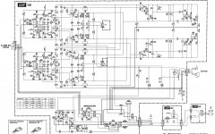
Attached relevant section of schematic.
Its trying to output +57 into the speakers, but thankfully its inbuilt protection wont energise its output relay. (saving the speakers)
EDIT. the main rectified rails are +/- 70v, the smaller section is +/- 15v after regs (~22v before regs)
The extra + voltage is on both bass and tweeter outputs.
All transistors have been removed, tested/compared as ok.
Ive tested a lot of the resistors and capacitors feeding from the positive rail, and all are ok.
Please, what am I missing ?
Attached relevant section of schematic.
Attachments
Last edited:
It is something similar with a class H amplifier?
I don't know. But it doesn't look quite like the normal a/b amps I've worked on.
Have you checked the negative rail and drives?
I did check a few voltages here and there, but I'm struggling to make sense out of the schematic.
I have removed and tested every single transistor.
And all test fine. Well, as far as i can tell anyway.
None are shorted and all of each type measure the same as each other.
I'm doing my powered up testing without the driver transistors in place.
and im getting such strange voltages on their solder pads.
60 / 70 +/-.
The thing that keeps throwing me is its both the high and low frequency amp sections that are effected.
I thought it might be a missing earth issue, but I cant find one.
On the amplifier, connector 201, is there continuity between pins 2 and 5? This is your ground for both amplifiers and as such must be grounded.
Yep saw that one.
I did have a jumper across them (pin 2 goes to power supply earth)
Didn't make much if any difference.
The input board that is connected through cn201 pin 2 & 5 are connected together.
I thought there might be voltage going into it through there, nope, 0v.
I did have a jumper across them (pin 2 goes to power supply earth)
Didn't make much if any difference.
The input board that is connected through cn201 pin 2 & 5 are connected together.
I thought there might be voltage going into it through there, nope, 0v.
This amplifier using "EEEngine" technology. A kind of tracking D class+AB output stages. There are convetional class AB output stage on the left side, and the switching part on the right side of the schematic.
Sajti
Sajti
sesebe - just woke up an hour ago, working on it as i type this. will post pic shortly...
sajti - ewww, no wonder I cant understand the schematic, thank you.
sajti - ewww, no wonder I cant understand the schematic, thank you.
Sesebe
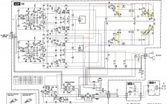
Voltages as pic.
All yellow circled components test perfectly fine
Test conditions;
No speakers connected. (Relay not engaging)
Ref to speaker/power supply gnd.
All transistors reinstalled.
pin 2 & 5 of CN201 joined together (gnd trace for twtr and bass section inputs)
tweeter output is 0.0v
bass output is +55v
EDIT, I no longer have a cro sorry. threw it out as it was getting unreliable and I can't afford to replace it.
Attachments
Hi,
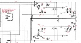
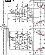
check the yellow components and the change capacitors (the best way to check the capacitors).
If you do not find the problem, remove the red component's (transistors and diodes).
In this way you disconnect the power stage and "EEEngine" technology.
Check voltage in blue points and correct the VAS stages.
good luck!
Attachments
Sesebe, many thanks for your help.
Changed the 4x 4.7uf caps, no fix.
Yellow circle - Had to lift the legs of r249/250/251/252 to get accurate reading, but all parts in the yellow test fine.
Without removing the bits in red;
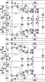
voltage across c221 = 0
voltage across c222 = 3.5
from ground;
c221 +61v on either side
c222 -1.7 on the neg side and +1.7 on the pos side
And just cause the pic is a bit blurry..
c221 is at the top of the diagram 10uf 25v
c222 is at the bottom of the digram 10uf 25v
EDIT added pic
Changed the 4x 4.7uf caps, no fix.
Yellow circle - Had to lift the legs of r249/250/251/252 to get accurate reading, but all parts in the yellow test fine.
Without removing the bits in red;
voltage across c221 = 0
voltage across c222 = 3.5
from ground;
c221 +61v on either side
c222 -1.7 on the neg side and +1.7 on the pos side
And just cause the pic is a bit blurry..
c221 is at the top of the diagram 10uf 25v
c222 is at the bottom of the digram 10uf 25v
EDIT added pic
Attachments
Last edited:
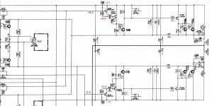
And with the circled parts removed.
The relay now kicks in and we have 0.04 and 0.05 on the speaker out connector.
Hooray, were getting somewhere...
EDIT, oh yes..
voltages across ;
c221 = 0.0
c222 = 3.5
The relay now kicks in and we have 0.04 and 0.05 on the speaker out connector.
Hooray, were getting somewhere...
EDIT, oh yes..
voltages across ;
c221 = 0.0
c222 = 3.5
Attachments

Last edited:
Hi,
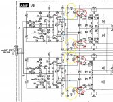
In thread 11 with all transistors installed you show that the base of Q238 it read +57, means that the base of Q237 it is also +57 means the the base of Q235 it is +57 and if it is +57 that is what it is causing the output read +57. Can you check the base of Q235 and post the reading? If it is +57 you need to back track to see why it is +57 volts.
In thread 11 with all transistors installed you show that the base of Q238 it read +57, means that the base of Q237 it is also +57 means the the base of Q235 it is +57 and if it is +57 that is what it is causing the output read +57. Can you check the base of Q235 and post the reading? If it is +57 you need to back track to see why it is +57 volts.
Hi Tuaro0221.
As requested..
These voltages are with q221/223/222/224 d212/214/211/213 removed.
I think, that the fault is in the front end, this "eeengine", as with those above bits removed, that isolates that eee from the amp section. Yes ?
As requested..
These voltages are with q221/223/222/224 d212/214/211/213 removed.
I think, that the fault is in the front end, this "eeengine", as with those above bits removed, that isolates that eee from the amp section. Yes ?
Attachments
Last edited:
Hi Tuaro0221.
As requested..
These voltages are with q221/223/222/224 d212/214/211/213 removed.
I think, that the fault is in the front end, this "eeengine", as with those above bits removed, that isolates that eee from the amp section. Yes ?
Yes. The switching looks well working. Now You have to check the input stage.
Sajti

Ta.
I shall re check them, if i have replacements, I shall swap them out.
Is the different voltage across c221 and c222 significant ?
I shall re check them, if i have replacements, I shall swap them out.
Is the different voltage across c221 and c222 significant ?
- Status
- Not open for further replies.
- Home
- Amplifiers
- Solid State
- Help troubleshooting yamaha ms400 please