Is the different voltage across c221 and c222 significant ?
Currently not. This is the bias voltage of the output stage. But as the driver stage is faulty it's not very important now.
Anyway it's a good information to identify the problem. 0V means, that no bias on the VAS stage, of the bias transistor is faulty (short circuit), but that is very rare.
So I would check all the DC voltages in the faulty driver stage.
Sajti

Hi,
can You please check the voltages of the differetial input stage on the faulty side too?
Sajti
can You please check the voltages of the differetial input stage on the faulty side too?
Sajti
Hi,
can You please check the voltages of the differetial input stage on the faulty side too?
Sajti
Sorry, i forgot to put them in.
the voltages around q205 / q206 - c209 / c210 - r210 / r212 are within the margin for any error.
also, i rechecked q221 223 222 224 all test the exact same.
i shall now go and do the q219 q211 c217 bits...
Sorry, i forgot to put them in.
the voltages around q205 / q206 - c209 / c210 - r210 / r212 are within the margin for any error.
What do You mean "within the margin for any error"? It would be nice to know why the 2 amplifiers are hanging on different rail...
Sajti
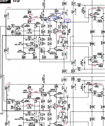
See image:
Check (change Q219, Q211), remove (for test) C217.
Sadly I dont have any replacement transistors available at the moment.
I removed and retested them, they measure ok.
Not that that guarantees they are ok.
voltages on all legs of q219 and q211 are within 0.5v of each other at +68v
removing c217 makes no difference at all.
I will swap q219 q211 with the other channel as a better test.
What do You mean "within the margin for any error"? It would be nice to know why the 2 amplifiers are hanging on different rail...
Sajti
I'm sorry, the differences are so small i didnt think it mattered.
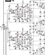
I have put the missing voltages in to this pic.
EDIT, sorry, wrong pic.
Attachments
Last edited:
Thanks!
It looks, that we need to check all other voltages, because the base of Q207 has higher voltage than the base of Q203, which should push the output stage towards to the negatíve rail, instead of the current situation.
I would measure all other voltages on this circuit including the VAS stage as recommended.
Sajti
ahhhhhh if your refering to the 0 and .047 at c209, thats the voltage on c209.
and the lower section, the 0 and .06 is is for c210.
i really should have made that clearer.
and the lower section, the 0 and .06 is is for c210.
i really should have made that clearer.
What is the voltage in base of Q211?
Do you measure to check if the voltages are like I show with blue (B-E on transistors)?
What it is hapend with the voltage if you short B-E at Q219?
Do you measure to check if the voltages are like I show with blue (B-E on transistors)?
What it is hapend with the voltage if you short B-E at Q219?
What is the voltage in base of Q211?
Do you measure to check if the voltages are like I show with blue (B-E on transistors)?
What it is hapend with the voltage if you short B-E at Q219?
base and emitter and collector of q211 is +68
base and emitter and collector of q219 is +68
yes, really, as if their shorted, yet they test fine when removed and tested with a dmm.
And when i remove c217, they stay the exact same voltages.
Put the DMM between pins not between pin and GND, 0.5-0.7V on 200V scale is not visible, it is in the error limits of DMM.
Do you short B-E at Q219?
You say that is +68V but in post 27 in collector you measure +70V. Please thake care how you measure!
Do you short B-E at Q219?
You say that is +68V but in post 27 in collector you measure +70V. Please thake care how you measure!
ahhhhhh if your refering to the 0 and .047 at c209, thats the voltage on c209.
and the lower section, the 0 and .06 is is for c210.
i really should have made that clearer.
OK, no problem.
It would be big help, if You can measure all the pins of the following transistors:
Q203
Q207
Q213
Q216
And all refering to the ground. My feeling, that one of 213 or 216 is faulty.
Sajti
ahhhhhh if your refering to the 0 and .047 at c209, thats the voltage on c209.
and the lower section, the 0 and .06 is is for c210.
That is not a mistake, the problem is still exist. The output should be on the negative rail, with this values.
Sajti
Put the DMM between pins not between pin and GND, 0.5-0.7V on 200V scale is not visible, it is in the error limits of DMM.
Do you short B-E at Q219?
You say that is +68V but in post 27 in collector you measure +70V. Please thake care how you measure!
I shall recheck as per your advise.
meter is a fluke 179.
mains voltage here has large variance and can be unstable, so things can change minute to minute.
power supply section of this amp is not exactly high end 😀
OK, no problem.
It would be big help, if You can measure all the pins of the following transistors:
Q203
Q207
Q213
Q216
And all refering to the ground. My feeling, that one of 213 or 216 is faulty.
Sajti
I shall do these as well 🙂
Many thanks to both of you 😀
I shall report back shortly.
sesebe.
between pins.
q211;
b/e +0.269 (q219 shorted b/e gives q211 b/e +0.916)
q219;
b/e +0.653
q219 collector +69 to +70 (varies with mains fluctuation)
.......................................
sajti.
with reference to gnd..
' ' ' q203 ' ' ' q207 ' ' ' q213 ' ' ' q216
b ' +0.029 ' +0.04 ' ' ' -69 ' ' ' ' -69
c ' ' -69.5 ' ' ' -69.5 ' ' -71 ' ' ' ' +70
e ' ' +0.6 ' ' ' +0.6 ' ' ' -70 ' ' ' ' -71
sajti.
with reference to gnd..
' ' ' q203 ' ' ' q207 ' ' ' q213 ' ' ' q216
b ' +0.029 ' +0.04 ' ' ' -69 ' ' ' ' -69
c ' ' -69.5 ' ' ' -69.5 ' ' -71 ' ' ' ' +70
e ' ' +0.6 ' ' ' +0.6 ' ' ' -70 ' ' ' ' -71
Thanks!
The input stage looks fine. The Q213-216 maybe interesting. Can You check the voltages between the pins too?
And can You please check the voltage across the R207 213?
Sajti
Thanks!
The input stage looks fine. The Q213-216 maybe interesting. Can You check the voltages between the pins too?
And can You please check the voltage across the R207 213?
Sajti
Welcome 😀
q213 b/e -1.5
q216 b/e +0.16 <- that fluctuates between 0.14 and 0.18 but seems to be mostly +0.16
across r207 0.29
across r213 0.291
Welcome 😀
q213 b/e -1.5
q216 b/e +0.16 <- that fluctuates between 0.14 and 0.18 but seems to be mostly +0.16
across r207 0.29
across r213 0.291
This:q213 b/e -1.5 looks too much. Which is the positive?
Sajti
had the neg lead on the base of q213.
actually wasnt sure if it mattered, so i've been doing all 'pin' b/e tests with neg on base of the transistor under test.
actually wasnt sure if it mattered, so i've been doing all 'pin' b/e tests with neg on base of the transistor under test.
Last edited:
- Status
- Not open for further replies.
- Home
- Amplifiers
- Solid State
- Help troubleshooting yamaha ms400 please