had the neg lead on the base of q213.
actually wasnt sure if it mattered, so i've been doing all 'pin' b/e tests with neg on base of that transistor.
Than I'm a bit confused. 1.5V too much for Vbe, especially opening direction. But if the BE diode is opened in the Q213, than Q216 should be turn on fully, and the output should be on -70V, not +70.
Sajti
LOL.
If your confused, how do you think poor little me is coping 😀
I'm totally lost..
Past my bed time.
Was up till 12.30 last night, its now 11.20pm here, while i go and try to sleep, please feel free to discuss this yama monster between yourselves 😉
I am extremely grateful for all the help and advice I have gotten from yourselves and others on this forum.
sesebe.
between pins.
q211;
b/e +0.269 (q219 shorted b/e gives q211 b/e +0.916)
q219;
b/e +0.653
q219 collector +69 to +70 (varies with mains fluctuation)
I was interested about the voltage in collector of Q219 with B-E shorted on Q219.
Now the voltage C-E on Q219 is allmost 0V, ~ +69V to GND.
With the short B-E on Q219, the voltage must drop to 0V or even negative voltage (if the transistor it is OK).
LOL.
If your confused, how do you think poor little me is coping 😀
I'm totally lost..
Past my bed time.
Was up till 12.30 last night, its now 11.20pm here, while i go and try to sleep, please feel free to discuss this yama monster between yourselves 😉
I am extremely grateful for all the help and advice I have gotten from yourselves and others on this forum.
Maybe we do some more test tomorrow. Good night! 🙂
Sajti
Hi,
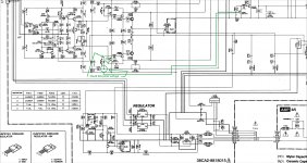
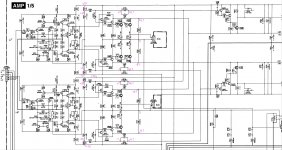
Attached is the schematic for thread 11. I did some note for you to look at it. I noticed that the -57 volts it read -5.7 volts and it should be -57. I think it should read same as the + 57 volts. Can you do the same test again and check the base voltages of Q236, Q237 and Q238.
Attached is the schematic for thread 11. I did some note for you to look at it. I noticed that the -57 volts it read -5.7 volts and it should be -57. I think it should read same as the + 57 volts. Can you do the same test again and check the base voltages of Q236, Q237 and Q238.
Attachments

Hi,
Attached is the schematic for thread 11. I did some note for you to look at it. I noticed that the -57 volts it read -5.7 volts and it should be -57. I think it should read same as the + 57 volts. Can you do the same test again and check the base voltages of Q236, Q237 and Q238.
For the moment, the problem is not there... and the "EEEngine" technology part of the schematic seems to work fine, but anyhow can't be tested if the rest of the amplifier is not working....
Hi,
Attached is the schematic for thread 11. I did some note for you to look at it. I noticed that the -57 volts it read -5.7 volts and it should be -57. I think it should read same as the + 57 volts. Can you do the same test again and check the base voltages of Q236, Q237 and Q238.
Pic.
Blue voltages are this mornings readings.
These are with the currently removed q221/223/222/224 d212/214/211/213 c217
These base readings, at 'switch on' start at about 60v and rapidly (10 seconds) drop to the reported voltages.
Attachments

Hi,
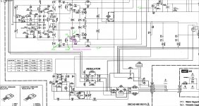
Sorry that I am asking too much but can you post the schematic that shows who is feeding the voltage to the base of Q236. I think it should be -57 volts.
Sorry that I am asking too much but can you post the schematic that shows who is feeding the voltage to the base of Q236. I think it should be -57 volts.
Ask what ever you wish for.
Your doing me an awesome service by helping me.
To post an image or test some voltages etc is no issue 🙂
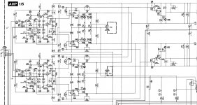
Also refer first post, that has the entire section, but due to size limits might be a touch blurry.
Im happy to zoom in and hi res any section needed.
EDIT, and heres the bottom half of that pic showing the full power supply section.
Your doing me an awesome service by helping me.
To post an image or test some voltages etc is no issue 🙂
Also refer first post, that has the entire section, but due to size limits might be a touch blurry.
Im happy to zoom in and hi res any section needed.
EDIT, and heres the bottom half of that pic showing the full power supply section.
Attachments

Last edited:
Hi,
I need you do another voltage check. I overlooked that the negative voltage can be disable from the other channel. Attached is the schematic with the point to check. Maybe we need to follow the same voltage pattern in the positive side to have an idea how it works since it is working Okay.
I need you do another voltage check. I overlooked that the negative voltage can be disable from the other channel. Attached is the schematic with the point to check. Maybe we need to follow the same voltage pattern in the positive side to have an idea how it works since it is working Okay.
Attachments
Hi,
All the reading matched each one. When you do the test do you have all the transistors out or all in. Another question what happened when you power ON the amplifier with all the transistors in. I think we may need to do the test with all the transistors installed and do the same reading that we did.
All the reading matched each one. When you do the test do you have all the transistors out or all in. Another question what happened when you power ON the amplifier with all the transistors in. I think we may need to do the test with all the transistors installed and do the same reading that we did.
Hi,
I would like if you can repeat the test you did in thread 11 and read the bases voltage of the fallowing transistors for comparison. We know that the positive rails it is working OKAY. The negative rails is the one reading bad -5.7 volt and it should be -57 volt same as the positive rail. By doing these checks we maybe able to find out where is the problem or what it is causing the negative rails voltage to read -5.7 volt.
Positive rails Negative rails
Q235 Q236
Q237 Q237
Q238 Q238
Q239 Q240
Q240 Q241
Q241 Q239
That was done with q221/223/222/224 - d212/214/211/213 - c217 removed.
All other devices are in.
With this, the speaker relay operates within a few seconds, and I have well under 0.5v on the speaker outputs.
When all components are in place, I get about +55v on the bass driver output, also the output speaker relay will not activate.
All other devices are in.
With this, the speaker relay operates within a few seconds, and I have well under 0.5v on the speaker outputs.
When all components are in place, I get about +55v on the bass driver output, also the output speaker relay will not activate.
Ok, so youd like me to reinstall all components, then check the base voltages of;
Positive rails Negative rails
Q235 Q236
Q237 Q237
Q238 Q238
Q239 Q240
Q240 Q241
Q241 Q239
I shall report back once done 🙂
Positive rails Negative rails
Q235 Q236
Q237 Q237
Q238 Q238
Q239 Q240
Q240 Q241
Q241 Q239
I shall report back once done 🙂
Hi,
just one idea:
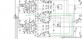
Can You check the voltages around Q213, and 216 refering to the -71V, including the voltage across the 330ohm emitter resistor.
Sajti
just one idea:
Can You check the voltages around Q213, and 216 refering to the -71V, including the voltage across the 330ohm emitter resistor.
Sajti
yup. shall do that first, then ill start on tauros request..
EDIT.
Sajti.
voltage across the 4x 330ohm emiter resistors r257 258 259 260 are all 0.2v
and with -71v reference;
q213
b +2.2
c +0.2
e 0
q216
b 0
c +141
e +0.2
EDIT.
Sajti.
voltage across the 4x 330ohm emiter resistors r257 258 259 260 are all 0.2v
and with -71v reference;
q213
b +2.2
c +0.2
e 0
q216
b 0
c +141
e +0.2
Last edited:
Hi,
I would like if you can repeat the test you did in thread 11 and read the bases voltage of the fallowing transistors for comparison. We know that the positive rails it is working OKAY. The negative rails is the one reading bad -5.7 volt and it should be -57 volt same as the positive rail. By doing these checks we maybe able to find out where is the problem or what it is causing the negative rails voltage to read -5.7 volt.
Positive rails Negative rails
Q235 Q236
Q237 Q237
Q238 Q238
Q239 Q240
Q240 Q241
Q241 Q239
It's already done in post 11. And the voltages looks OK, as the bass amp failure push the EEEngine towards the positive rails.
Sajti
- Status
- Not open for further replies.
- Home
- Amplifiers
- Solid State
- Help troubleshooting yamaha ms400 please