It's already done in post 11. And the voltages looks OK, as the bass amp failure push the EEEngine towards the positive rails.
Sajti
ok, so I don't need to do this test by the sound of it.
And just in case you missed the edit to post 59..
Sajti.
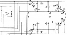
voltage across the 4x 330ohm emiter resistors r257 258 259 260 are all 0.2v
and with -71v reference;
q213
b +2.2
c +0.2
e 0
q216
b 0
c +141
e +0.2
sesebe.
between pins.
q211;
b/e +0.269 (q219 shorted b/e gives q211 b/e +0.916)
q219;
b/e +0.653
q219 collector +69 to +70 (varies with mains fluctuation)
I was interested about the voltage in collector of Q219 with B-E shorted on Q219.
Now the voltage C-E on Q219 is allmost 0V, ~ +69V to GND.
With the short B-E on Q219, the voltage must drop to 0V or even negative voltage (if the transistor it is OK).
Hi can you repeat this test measuring the volatge drop on transistor (C-E on Q219 ) in the 2 cases?
Sesebe.
c/e of q211 -0.652
c/e of q219 +0.017
with b/e shorted on q219
c/e of q211 0.0
c/e of q219 +6.4
Thats with neg lead on collectors.
c/e of q211 -0.652
c/e of q219 +0.017
with b/e shorted on q219
c/e of q211 0.0
c/e of q219 +6.4
Thats with neg lead on collectors.
ok, so I don't need to do this test by the sound of it.
And just in case you missed the edit to post 59..
Sajti.
voltage across the 4x 330ohm emiter resistors r257 258 259 260 are all 0.2v
and with -71v reference;
q213
b +2.2
c +0.2
e 0
q216
b 0
c +141
e +0.2
Thank You!
It still looks interesting.
I would change q213, but I'm not 100% sure.
Maybe we can measure the same voltage in the wworking channel to compare.
Sajti
sajti.
with -71 ref
q214
b +3.1
c +2.3
e +3
q218
b +3
c +2.3
e +2.3
It looks absolutely good, and well working.
Sajti
Change Q213 with any small signal PNP transistor for tests the idea of Q213 open.
I think that this is the problem.
I think that this is the problem.
Thank you! and the right down side?!?
I do not have the service manual....and, maybe, after you will repair the input stages, will be neccesary to check the eeengine side....
I do not have the service manual....and, maybe, after you will repair the input stages, will be neccesary to check the eeengine side....
I shall see what i have to swap in for q213..
I can do tighter crops of the schematic if needed.
Im just screen printing from the service pdf.
This is just a cheap realisation of EEEngine technology. The biggest Yamaha amps use MOSFETs for switching, for a few kW output power....
Sajti
Thank you! and the right down side?!?
I do not have the service manual....and, maybe, after you will repair the input stages, will be neccesary to check the eeengine side....
sent you a pm.
i have some 2sa733 that i can use as test transistors ...
ill do that shortly.
if anyone would like a copy of this ms400 service manual, pm me your email adress.
its a 4.3mg pdf.
its a 4.3mg pdf.
Awwwwwwwwww
swapped out q213 (2sa1015) with a 2sa733 (almost the same specs) and ........
Nope.
no different to before.
all voltages are exactly the same.
swapped out q213 (2sa1015) with a 2sa733 (almost the same specs) and ........
Nope.
no different to before.
all voltages are exactly the same.
Awwwwwwwwww
swapped out q213 (2sa1015) with a 2sa733 (almost the same specs) and ........
Nope.
no different to before.
all voltages are exactly the same.
Bad news 🙁
I have no idea how to continue.
Sajti
ok, so I don't need to do this test by the sound of it.
And just in case you missed the edit to post 59..
Sajti.
voltage across the 4x 330ohm emiter resistors r257 258 259 260 are all 0.2v
and with -71v reference;
q213
b +2.2
c +0.2
e 0
q216
b 0
c +141
e +0.2
Ops I made mistake to not read carefully the post. I mean the 330ohm resistor at the emitter of q216. Sorry!
Sajti
- Status
- Not open for further replies.
- Home
- Amplifiers
- Solid State
- Help troubleshooting yamaha ms400 please