If you have 9.5 volts here as well then something is open circuit.
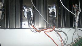
Has a wire come off somewhere in the feed to the base of the outputs ? Check the continuity of all the wiring to the outputs carefully (with it off).
Has a wire come off somewhere in the feed to the base of the outputs ? Check the continuity of all the wiring to the outputs carefully (with it off).
E/E- 9.5V
Its something basic then. Switch it off and check that the 4.7 ohms connect to the bases of the outputs.
The other thought I have is that the output transistors are open circuit base to emitter and if that were so then it points to them being fakes. You can prove that by measuring across the base and emitter of the outputs with the amp on. Anything over 0.7 volts and they are faulty. That is really all we are doing now with the E to E- measurement so unless there is a physical break like a broken wire....
So If that proves to be the case and the devices are open circuit then I would say almost with 100% certainty that they are not genuine devices. What did we fit there ? Was it MJ21193/4
I'll have to leave it for now... and be careful measuring with it on.
Just so I'm sure with your readings of E to E- You get 9.5 volts with the red lead on E and the black lead on E-
Well this is a very strange problem because nothing seems to have gone up in smoke and there is no significant offset etc.
This 9.5 volt reading on E to E- Can you confirm that it is plus 9.5 volts when the red lead is on E and the black on E-
This 9.5 volt reading on E to E- Can you confirm that it is plus 9.5 volts when the red lead is on E and the black on E-
Well this is a very strange problem because nothing seems to have gone up in smoke and there is no significant offset etc.
This 9.5 volt reading on E to E- Can you confirm that it is plus 9.5 volts when the red lead is on E and the black on E-
E to E- it's -9.7, same value for D to D-
OK, so its minus 9.7 thats interesting 🙂
That puts a whole new spin on it all. Lets try and be more methodical because I've not been very clear with some of the instructions for you. The readings that you gave in post #355 which were these,
A and A- 3.05V
B and B- 7.05V
C and C- 7.85V
D and D- 9.5V
With the red lead on A and the black lead on A- was it plus 3.05 or minus 3.05
And the same for the others. The red lead on B and black on B- Was it plus 7.05 or minus 7.05
Its looking like it probably is one of the drivers or pre drivers that could be open circuit but lets cover all the ground. I would also not have any speakers connected... not worth the risk.
And the same for C
Just to clarify, I'm doing all the operations with the amp connected through the bulb and also without the speakers.
A to A- 4.2V
B to B- 26.4V
C to C- -42.5V
D to D- -31V
E to E- -30.7V
Those should be correct, forget about the previous ones since I think I made some confusion between base and emitter (not so easy for me to pass from scheme to the board, the board figure in the manual is the inverse of my channel plus the MJE350 are different in respect to the originals) Now I triple checked everything and I think I didn't made any mistakes
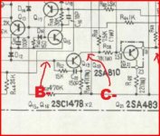
Thats great. A to A- is reasonable. Things really go amiss with the B and C readings. With plus 26 volts across B and B- you should really see that reflected across to C and C- and its not. It could be either an open or a leaky transistor so we need to try and pin it down.
Let me try and explain that a bit better. Voltage B and B- is obtained from A and A- so on the face of it it appears there is a problem with or around Q18 and Q19
So we need a more few quick tests around these transistors. This time connect your black meter lead to ground and leave it connected there.
Measure on B and C, and B- and C-
So thats four readings, all with the black lead on ground.
B can't get a stable result (move between 1.6V and 1.8V)
C can't get a stable result (move between 2.3V and 2.5V)
B- -23.4V
C- 44.7V
C can't get a stable result (move between 2.3V and 2.5V)
B- -23.4V
C- 44.7V
The stand out result there is B- to C- Thats showing around 67 volts between those two points. Do you agree ? Look at the circuit and those points are actually measuring across the base and emitter junction of Q19. That transistor is definitely faulty to give that result. Whether there are more problems remains to be seen.
Pleased to see you are using the bulb too.
Pleased to see you are using the bulb too.
Attachments
Is it possible that the MJE350 is not the right substitute? (Q18 and Q19 are MJE350 while the rest is original)
Well they were the best we could come up with at the time if you remember but they should OK for those locations (Q18 MJE340, npn).
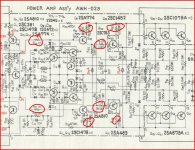
It is a dificult fault to diagnose without having the unit to actually work on... far more difficult than rebuilding it all as we did before. That transistor is faulty though given those readings. I would recommend you check (with it off) these resistors too.
What did we fit for Q20 and Q21 ? Was that MJE340/350 as well ? Or did we leave the originals ?
Replacing that transistor has to be the next step though.
Attachments
My bad Q18 is MJ340 and Q19 MJ350
For Q20 and Q21 we used MJE15032G and MJE15033G
I have a couple of them available and some MJ340/350 too
For Q20 and Q21 we used MJE15032G and MJE15033G
I have a couple of them available and some MJ340/350 too
I'm tempted to say replace both MJE340 and the MJE350. Leave Q20 and Q21 as they are.
If you altered the bias (I think you said you did) then set it back on the minimum setting for testing. You should be OK with the bulb though.
Lets see what replacing those transistors does. When its all working again we could look at some alternatives but for now lets just concentrate on getting it back to where it was before.
R58 40ohm
R54 48ohm
R66 impossible to read (constantly grow) 2.8k
R53 48ohm
R57 41 ohm
R65 23.5ohm
R35 (in reality is R36 on the board) 0.91k
R37 1k
Out of all this resistors only R35-37 are new, all the other are original
R54 48ohm
R66 impossible to read (constantly grow) 2.8k
R53 48ohm
R57 41 ohm
R65 23.5ohm
R35 (in reality is R36 on the board) 0.91k
R37 1k
Out of all this resistors only R35-37 are new, all the other are original
R66 looks faulty. Its a low value resistor and should read OK in circuit. If you've a good connection with the meter leads to the resistor and it still reads faulty then take it out and check. If it is faulty then we need to look at replacing the four transistors. Also if the resistor is faulty then does Q21 read short circuit between collector (the pin the resistor goes to) and either of the other two pins.
- Status
- Not open for further replies.
- Home
- Amplifiers
- Solid State
- Help repairing Pioneer M3