Looks like you are getting somewhere snowjx  .. yes just use jumpers where you are in doubt of the tracks, or crape off the green coating layer on the tracks and use flux + solder to ensure connection.
Don't know why you cll it carbon tracks ... it's copper, with a layer of green epoxy paint/coating on top.
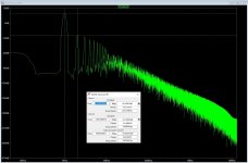
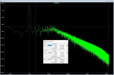
Just messed a bit with the simulation, and there are plenty of ways to improve the performance without changing the circuit much.
Firstly changing the output transistors from 2N3055/MJE2955 to 2SC5200/2SA1943 gives a ca 20 db improvement.
Increasing the current in the input stage to 1.5mA, Increasing the amplification in input stage, and increasing the current in the driver stage (this will require small heatsinks on the DB139/BD140) gives another +20 db. All theis at 1kHz and ca 14Vpk output / 0.775 Vpk input.
Increasing the currint in the input stage will require 2 small caps as shown to eliminate starting oscillation.
Better than increasing the current in the output and getting so much heat you need a fan.
The above will have to be tested further also ensuring better performance at higher freq, ensuring no oscillation etc. .... most can be done in sim, but using an oscilloscope at the end to ensure no oscillation
PS. No sim is better than the models used, so don't trust the overall figures, but for sure the trend ... if it increases the distortion in sim, it will most likely do the same in reality
PPS. An then there is the bigger question, if we can actually hear the difference .... I highly doubt it 😉 ..... but it's fun anyway 😀
.. yes just use jumpers where you are in doubt of the tracks, or crape off the green coating layer on the tracks and use flux + solder to ensure connection.Don't know why you cll it carbon tracks ... it's copper, with a layer of green epoxy paint/coating on top.
Just messed a bit with the simulation, and there are plenty of ways to improve the performance without changing the circuit much.
Firstly changing the output transistors from 2N3055/MJE2955 to 2SC5200/2SA1943 gives a ca 20 db improvement.
Increasing the current in the input stage to 1.5mA, Increasing the amplification in input stage, and increasing the current in the driver stage (this will require small heatsinks on the DB139/BD140) gives another +20 db. All theis at 1kHz and ca 14Vpk output / 0.775 Vpk input.
Increasing the currint in the input stage will require 2 small caps as shown to eliminate starting oscillation.
Better than increasing the current in the output and getting so much heat you need a fan.
The above will have to be tested further also ensuring better performance at higher freq, ensuring no oscillation etc. .... most can be done in sim, but using an oscilloscope at the end to ensure no oscillation
PS. No sim is better than the models used, so don't trust the overall figures, but for sure the trend ... if it increases the distortion in sim, it will most likely do the same in reality
PPS. An then there is the bigger question, if we can actually hear the difference .... I highly doubt it 😉 ..... but it's fun anyway 😀
Attachments
not all resitive paths or leakages from carbon contamination will show up if your meter is set to a low resistance range, looking for higher impedance paths using higher scales could be revealing.
Ah, I see what you meannot all resitive paths or leakages from carbon contamination will show up if your meter is set to a low resistance range, looking for higher impedance paths using higher scales could be revealing.
The "carbon tracks" are reference to epoxy substrate material that is so damaged by heat that it is reduced to "carbon" conductor.Don't know why you cll it carbon tracks ... it's copper, with a layer of green epoxy paint/coating on top.
Best,
Steve
I am currently using MJ21193/21194G as output transistor, I have bought 4 pairs of them, so not likely to swap them. These transistors looks good to me as simulation shows without other improvements you mentioned, I still got not bad distortion figure. I found the spice model of these transistors from onsemi website.Looks like you are getting somewhere snowjx
Don't know why you cll it carbon tracks ... it's copper, with a layer of green epoxy paint/coating on top.
Just messed a bit with the simulation, and there are plenty of ways to improve the performance without changing the circuit much.
Firstly changing the output transistors from 2N3055/MJE2955 to 2SC5200/2SA1943 gives a ca 20 db improvement.
Increasing the current in the input stage to 1.5mA, Increasing the amplification in input stage, and increasing the current in the driver stage (this will require small heatsinks on the DB139/BD140) gives another +20 db. All theis at 1kHz and ca 14Vpk output / 0.775 Vpk input.
Increasing the currint in the input stage will require 2 small caps as shown to eliminate starting oscillation.
Better than increasing the current in the output and getting so much heat you need a fan.
The above will have to be tested further also ensuring better performance at higher freq, ensuring no oscillation etc. .... most can be done in sim, but using an oscilloscope at the end to ensure no oscillation
PS. No sim is better than the models used, so don't trust the overall figures, but for sure the trend ... if it increases the distortion in sim, it will most likely do the same in reality
PPS. An then there is the bigger question, if we can actually hear the difference .... I highly doubt it 😉 ..... but it's fun anyway 😀
I will have a look into the improvements you suggested. Its quite fun to test things in the simulation. I never used simulation before, thank you for bring me into this wolrd.
I dont have much experience in the circuit design, so will be hesitant to change the original design in real world, in a risk of ruin something that I dont have experience to resolve. Will start the investigation in the simulation. To learn some knowledge and have some fun.
In terms of this amp itself, it obviously dont have very good spec of things like THD as modern amps have, but it does have some magic that sounded very nice to my experience. Maybe someone more knowledgable can explain why is that
I will try to do the same to the top part as well to see if I can bring the up and bottom part into balance.Your continuing experiments seem to add further evidence that you're on the right track. I agree with your conclusions.
I'm not sure how to advise you. You've got a lot of time and effort already invested in this board. I can recall similar experiences; as the board approaches the point of being a hopeless case, it's a bit liberating--- you can attempt bolder measures because there's little left to loose anyway. Success is sometimes the payoff.
Cutting suspicious tracks just beyond the burned areas and then jumpering the severed traces may be easier than trying to thoroughly excavate damaged material (and success more assured). If a lead of a sensitive component lies within a burned region, pull it out of the board and improvise a through-the-air connection. If you eventually get the amp performing as it should, then you can swap in close tolerance parts for better performance. BTW, your caps may already have adequately low leakage--- I didn't know what parts you have chosen.
If you get stuck in a particular, area-top or bottom, I'll try to offer advice.
Good luck!
This PCB to be honest is quite hopeless. The quality is quite bad from the beginning. After a few solder and desolder, a lot of place have contacts and tracks coming off the board. So I have to jump everywhere, plus they are mono blocks, that means I have another board to deal with. Quite a headache if that one also have same problem at least same burn marks are on the other board as well.
I actually found a new PCB without the power section, on chinese taobao site only sell for 2 dollars a pair(shipping them to overseas may cost 30 dollar alone), left and right channel. maybe worth considering buy a pair and place it on top of original PCB.
Ultimate option will be design a new one, in which case many things can be improved, including the improvements Baldin suggested.
Attachments


MJ21193/21194G probable almost as good as 2SC5200/2SA1943 .... thought you where using 2N3055/NJE2955 .... also TO3 fits right in 😉
What output transistors are the originals for MA50?
What output transistors are the originals for MA50?
Original ones are 2N3055/MJ2955MJ21193/21194G probable almost as good as 2SC5200/2SA1943 .... thought you where using 2N3055/NJE2955 .... also TO3 fits right in 😉
What output transistors are the originals for MA50?
- Home
- Amplifiers
- Solid State
- Help please, Musical Fidelity A1/MA50 one channel distorted after about 10 seconds