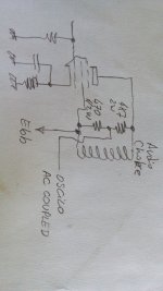
Triode's catode = 0.8v -with 1k towards gndWhich is the pentode's cathode voltage? And triode's cathode and plate voltages?
The DCR of the choke is usually under 100 ohm, so the voltage drop will be low too. DC voltage drop is unimportant, we are interested in the audio voltage drop. We can call it now the modulation choke.
If you have a signal generator, thus use it to check the gain and the linearity of the amplifier. Load the audio amp with a 3~5 Kohm @2W resistor in parallel to the choke to simulate the modulated amplifier load. Hook the oscilloscope AC coupled to PCL86 pentode plate and see where is it clipping or not. Perhaps we need to touch some parameters. If not a signal generator, use line voltage steped down with a transformer and filter out the majority of the thrash that comes with it: build a simple low pass filter with a series 100K resistor and a 0.1uF shunt capacitor. From it you will have a reasonably clean 50 or 60Hz sine signal.
Of course. Nothing new here. When the audio section be connected to the PCF802 and it be doing its job, we shall call it the modulator.
Triodes plate = 65v
Pentode's cathode = 9.3v -with 390ohm towards gnd
Instead of signal generator I ussualy use old cellphone (that I don't mind damaging) with test tones, if this is ok?
I have problem with oscilloscope, it can measure only up to 50vpk... yes I know I need to get something better ASAP, but prices are high...
Can I build some kind of divider network?
EDIT:
There are some schematics online for x20 probe, but based on what I have found, just using 10mOhm resistor in series on +probe should do the trick... What do you think?
Last edited:
Triode's catode = 0.8v -with 1k towards gnd
Triodes plate = 65v
Looks pretty fine.
Pentode's cathode = 9.3v -with 390ohm towards gnd
This too
Instead of signal generator I ussualy use old cellphone (that I don't mind damaging) with test tones, if this is ok?
Yes. I found a good signal generator for android a year ago.
Yes too. No need for compensating the attenuator here. What we are doing isn't a precision set. Use, for example a 4.7K @2W (no need for a single unit, make parallel/series combination if needed) and a 470R in series, the last to the +B point. You thus are building a 1:11 attenuator.I have problem with oscilloscope, it can measure only up to 50vpk... yes I know I need to get something better ASAP, but prices are high...
Can I build some kind of divider network?

Ok, just to check. I connect 470R between + probe and B+Looks pretty fine.
This too
Yes. I found a good signal generator for android a year ago.
Yes too. No need for compensating the attenuator here. What we are doing isn't a precision set. Use, for example a 4.7K @2W (no need for a single unit, make parallel/series combination if needed) and a 470R in series, the last to the +B point. You thus are building a 1:11 attenuator.
Then I connect 4.7k between +probe and measuring point?
Oh yes, that makes sense. And with that in mind do I still need load resistor or will this divider network act as a load?Better a pic. If your 'scope hasn't AC coupling, add a .1uF@400V in the tip.
Ok, got the resistors, will make progress after I get home from work.Yeah. They are doing two tasks. But use them (load and att) if you prefeer.
I did the test. They gave me wrong resistors at the store (470k instead of 470R). So I used 470k and 4.7k and another 4.7k for loadYeah. They are doing two tasks. But use them (load and att) if you prefeer.
There is some clipping after 3/4 volume and below around 4khz, but I'm not to concerned about it. There is no way mic will give such levels, at least without preamp.
I'm more concerned about the uneven level-voltage of the wave.

What do you think? I personaly would give it a try and solve it if this uneveness would be audible... Don't mind the voltages on the scope, they change as you change divisions -made in China.
As for linearity... I would be concerned if this would be ment for hifi, but lets say it's ok, not good, but ok. Pretty good between 3k and 15k.
Don't forget its an experimental device. So no need for extreme good quality.
Next steep is start building the RF final amp or modulated amplifier. This is the more important step.
We will need the plate tank. For it we will need the open plates (air dielectric) variable cap shown in the older posts, and build the inductance for the tank. Check with a DMM that rotor (rotable plates) and stator (fixed ones) don't touch themselves. Try it with some care.
Using the other plastic tube, make a couple of holes in the same form as the oscillator tank. Try to design the coil "squared", that is its diameter be equal to its long. It usualy gives the best Q. So put in it about 12 turns of the wire more or less equally distributed in the available width. When wiring into the circuit, keep their axis at right angles to minimize coupling (I refer oscillator and final tank).
The hot extreme of the coil, that is, the one wired to second gang and to the plate, try to put it at bottom of the coil. And the bypass capacitor at the cold side of the coil (0.01uF) must return as shortly as possible to the armature of the gang, and toguether, as short as possible to pentode's cathode. This minimizes "high RF current" loops.
Last edited:
Coil is wound and gang appears to be good.Don't forget its an experimental device. So no need for extreme good quality.
Next steep is start building the RF final amp or modulated amplifier. This is the more important step.
We will need the plate tank. For it we will need the open plates (air dielectric) variable cap shown in the older posts, and build the inductance for the tank. Check with a DMM that rotor (rotable plates) and stator (fixed ones) don't touch themselves. Try it with some care.
Using the other plastic tube, make a couple of holes in the same form as the oscillator tank. Try to design the coil "squared", that is its diameter be equal to its long. It usualy gives the best Q. So put in it about 12 turns of the wire more or less equally distributed in the available width. When wiring into the circuit, keep their axis at right angles to minimize coupling (I refer oscillator and final tank).
The hot extreme of the coil, that is, the one wired to second gang and to the plate, try to put it at bottom of the coil. And the bypass capacitor at the cold side of the coil (0.01uF) must return as shortly as possible to the armature of the gang, and toguether, as short as possible to pentode's cathode. This minimizes "high RF current" loops.

Should I use small or big section of gang?
What do you mean by keeping coils axis at right angle? Having both coil parallel? Or perpendicular to each other?
Would it be good like this?Perpendicular. Axis at 90° between them.
Respect to bigger gang try the larger one.

And schematic like this?

Last edited:
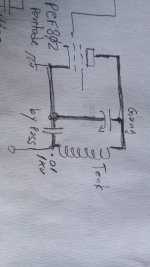
Coil & gang are wired in. Will post schematics shortly.When you have a moment, please send me a schematic showing mainly the component's value and important voltages at grids, cathodes and plates so I have an idea where we are sitted now. No urgent.


Ok. By now, leave the audio sector alone. Wire the screen and plate of the RF output. Use by moment a 100K @ 1W (or similar: 120K, 82K, 2 x 47K etc.) resistor for the 802's screen. It may be excessive, but as it will be the first time you manipulate a tuned amplifier, it is safe for you and the tube. Still no test it with DC because I need to say how to adjust it. Remeber wiring the milliammeter into the RF amplifier section. Unless you find another source of data more reliable than me 🤔 🙄.
Now I'll go to bed. We had 34°C today and I suffer a lot the hot weather. I prefeer 16 to 18°C for comfort.
Now I'll go to bed. We had 34°C today and I suffer a lot the hot weather. I prefeer 16 to 18°C for comfort.
- Home
- Amplifiers
- Tubes / Valves
- Help me put these tubes into good use... I need a project