Hy,
I had recently acquired some parts from and old enthusiast...
Among the parts I got there are some tubes, most look new, unused in original packaging. Also there some retro looking pot knobs and such...
I would like to build something with them, search had revealed that those are mostly TV tubes, but also that they can be used for radio, preamp, amp,...
First of all I am aware that isolation transformer is a must, I had learned that the hard way, when I fryed all the ground traces on my pc motherboard.
TUBE LIST:
PL504
PCF801
PCF802
ECH84
PCL805
PCL86
PCC88
There is 1 piece of each, sadly no pairs...
And there was one that would need to be identified. It was in PCL84 box, but its writen ECH and B3B4 on it... filament needs 15v to glow and filament pins are 4 and 5.
So far I had just tryed filaments, all tubes have nice orange glow.
I already have EL84 amplifier that I had build few years back. It could use some preamplification, so I tought I could swap EL84 for PCL86.
This is the schematic:

What would need to be done except of rising filament voltage to use PCL86 and benefit some gain?
Deciding if I will modify this amp would be the first step so we can know if I will continue either with EL84 or PCL86 into the new project...
For new project I was thinking either preamplifier (I wont need it if I modify my amp), Fm radio if possible? Or even better some sort of ham radio... I always wanted tube ham radio and I possible I would build that.
I'm open to suggestions,
Thank you
I had recently acquired some parts from and old enthusiast...
Among the parts I got there are some tubes, most look new, unused in original packaging. Also there some retro looking pot knobs and such...
I would like to build something with them, search had revealed that those are mostly TV tubes, but also that they can be used for radio, preamp, amp,...
First of all I am aware that isolation transformer is a must, I had learned that the hard way, when I fryed all the ground traces on my pc motherboard.
TUBE LIST:
PL504
PCF801
PCF802
ECH84
PCL805
PCL86
PCC88
There is 1 piece of each, sadly no pairs...
And there was one that would need to be identified. It was in PCL84 box, but its writen ECH and B3B4 on it... filament needs 15v to glow and filament pins are 4 and 5.
So far I had just tryed filaments, all tubes have nice orange glow.
I already have EL84 amplifier that I had build few years back. It could use some preamplification, so I tought I could swap EL84 for PCL86.
This is the schematic:
What would need to be done except of rising filament voltage to use PCL86 and benefit some gain?
Deciding if I will modify this amp would be the first step so we can know if I will continue either with EL84 or PCL86 into the new project...
For new project I was thinking either preamplifier (I wont need it if I modify my amp), Fm radio if possible? Or even better some sort of ham radio... I always wanted tube ham radio and I possible I would build that.
I'm open to suggestions,
Thank you
Last edited:

PL504: Push pull amp with low impedance OPT (2~3K), should be a good candidate to drive toroids, good in triode mode, but careful with screen voltage. UNSET is also an option, but I have not tried it yet.
PCL86: Good candidate for a variant of Tubelab's SPP, 10~12W should be achievable.
P* tubes require 300mA for heaters, voltage varies.
E* tubes require 6.3V.
PCL86: Good candidate for a variant of Tubelab's SPP, 10~12W should be achievable.
P* tubes require 300mA for heaters, voltage varies.
E* tubes require 6.3V.
Thank you both for information...
I have one piece of each tube, so sadly pushpull is out of reach...
As I already have an amp, I would like to go radio reception / transmission path...
A ham radio that I could also use as an amplifier would be my best wish...
It can be crude, just something that I can play with and get some functionality from it.
Maximum anode dissipation for the PCL86 tetrode is 9W (EL84 12W) therefore yo need to play with the cathode resistor to keep the idle anode power in check. You also have a high mu spare triode, giving you the possibility of adding an input stage and use negative feedback to keep distortion in check.....
I already have EL84 amplifier that I had build few years back. It could use some preamplification, so I tought I could swap EL84 for PCL86.
This is the schematic:
View attachment 1109831
What would need to be done except of rising filament voltage to use PCL86 and benefit some gain?
.....
Sorry, I have no experience with ham radio, which is bit out of scope here 🙂Thank you both for information...
I have one piece of each tube, so sadly pushpull is out of reach...
As I already have an amp, I would like to go radio reception / transmission path...
A ham radio that I could also use as an amplifier would be my best wish...
It can be crude, just something that I can play with and get some functionality from it.
Sorry, I have no experience with ham radio, which is bit out of scope here 🙂
Ok I need to do some homework reading / researching to find out what you are talking about here... I don't have much experience with tubes... Will do research and come back when things are more clear to me... Just to clarify things triode would be used for preamplification and pentode for amplification?Maximum anode dissipation for the PCL86 tetrode is 9W (EL84 12W) therefore yo need to play with the cathode resistor to keep the idle anode power in check. You also have a high mu spare triode, giving you the possibility of adding an input stage and use negative feedback to keep distortion in check.
About the ham radio... It would be better to search on some other forum as there is no category for radios right?
Yes, the idea is to use the PCL86 triode for pre-amplification and the pentode for the output stage.Ok I need to do some homework reading / researching to find out what you are talking about here... I don't have much experience with tubes... Will do research and come back when things are more clear to me... Just to clarify things triode would be used for preamplification and pentode for amplification?
....
There is a lot of good information at Merlin Blencowe's website:
Input stage with triode: http://www.valvewizard.co.uk/gainstage.html
Output stage single ended: http://www.valvewizard.co.uk/se.html
There is something called the Mullard Economical Amplifier, based on the ECL86 could be a good starting point:
http://www.r-type.org/articles/art-003g.htm
Something I should have mentioned first, since you don't have much experience with tubes:
High voltage kills! You have to be very careful when working, using the right equipment and following the rules:
https://www.diyaudio.com/community/threads/safety-practices-general-and-ultra-high-voltage.30172/
High voltage kills! You have to be very careful when working, using the right equipment and following the rules:
https://www.diyaudio.com/community/threads/safety-practices-general-and-ultra-high-voltage.30172/
CB radio band (27Mhz) can be used without licence, up to 12W in the UK:Have you callsign? One of them is legally needed to operate RF TX with more than 100mW usualy. Mine is LW1DSE since 1987.
"CB users must ensure they do not cause interference, and must not exceed the Transmitter Power Levels specified by Ofcom:
FM Modulation: 4 Watts
AM Modulation: 4 Watts
DSB & SSB: 12 Watts PEP"
CB transmissions here are disappeared here. First was replaced by VHF, then for beepers and now cell phones.
Having in mind that you have tubes designed for use with filaments in series and so not suitable for use from a transformer, probably from a TV, a possible use for them is:
PCF 802 TRIODE as crystal or Clapp oscillator at some desired frequency.
PCF 802 PENTODE as buffer (untuned choke loaded amplifier).
PL 504 final stage with, say, 300VDC as anode voltage.
PCL86 TRIODE as audio mic preamp.
PCL86 PENTODE as power amplifier for audio, and AM modulating the screen grid of PL504 via an audio choke and a dropping resistor and audio bypassed to '86's plate.
RF stages operated CLASS C with grid current.
Keep in mind that working with RF is pretty interesting but quite dangerous because POWER RF BURNS SKIN if improper conducted to a load.
Tubes at RF are one of the my first uses of them. I remember my first TX using a 6DQ6 plate & screen grid modulated by another, a 6U8 oscillating 1.6MHz, a 6BQ5 doubling to 3.5MHz and a 12AX7 used as mic preamp using crystal microphone. For the modulation using a choke from a ferroresonant stabilizer. As the inductance was too low, my colleagues said I have "voz de pito" (too many trebbles and few bass notes). But I was only 16 and I was satisfied with only maintain a dialog with friends LU6EHW and LU2DFD (both RIP) at rougly 1.2Km of distance every day 8AM several decades ago.
I don't have a call sign, but if I would put something together to have a working radio, I would take the test and get the licence.CB radio band (27Mhz) can be used without licence, up to 12W in the UK:
"CB users must ensure they do not cause interference, and must not exceed the Transmitter Power Levels specified by Ofcom:
FM Modulation: 4 Watts
AM Modulation: 4 Watts
DSB & SSB: 12 Watts PEP"
I like that Mullard economical amplifier. I will likely go that route, but will wait to see if I will use the tube for radio...
I went thru the safety thread you posted, I am aware of the dangers and I do / will follow the rules. I want to live.
I don't, but I would get it ASAP if I end with working radio.Have you callsign? One of them is legally needed to operate RF TX with more than 100mW usualy. Mine is LW1DSE since 1987.
Ok, I must do some research so I will be able to understand what you written.CB transmissions here are disappeared here. First was replaced by VHF, then for beepers and now cell phones.
Having in mind that you have tubes designed for use with filaments in series and so not suitable for use from a transformer, probably from a TV, a possible use for them is:
PCF 802 TRIODE as crystal or Clapp oscillator at some desired frequency.
PCF 802 PENTODE as buffer (untuned choke loaded amplifier).
PL 504 final stage with, say, 300VDC as anode voltage.
PCL86 TRIODE as audio mic preamp.
PCL86 PENTODE as power amplifier for audio, and AM modulating the screen grid of PL504 via an audio choke and a dropping resistor and audio bypassed to '86's plate.
RF stages operated CLASS C with grid current.
Keep in mind that working with RF is pretty interesting but quite dangerous because POWER RF BURNS SKIN if improper conducted to a load.
Tubes at RF are one of the my first uses of them. I remember my first TX using a 6DQ6 plate & screen grid modulated by another, a 6U8 oscillating 1.6MHz, a 6BQ5 doubling to 3.5MHz and a 12AX7 used as mic preamp using crystal microphone. For the modulation using a choke from a ferroresonant stabilizer. As the inductance was too low, my colleagues said I have "voz de pito" (too many trebbles and few bass notes). But I was only 16 and I was satisfied with only maintain a dialog with friends LU6EHW and LU2DFD (both RIP) at rougly 1.2Km of distance every day 8AM several decades ago.
If I understand correctly, I could build radio with my tubes? I understand that I need mic preamp and audio amp, I don't understand the actual RF part...
"POWER RF BURNS SKIN" if you touch it, or also over the air? From my head good practice would be to build grounded cage around the RF part?
EDIT: I'm reading about RF burns right now and if understand correctly, I can't get burned over the air? Only if I touch the antenna or RF output path, right?
Now I know the difference between RF burn or "ordinary" electric burn... ouch...
Last edited:
Yes. Think as an open microwave oven. Microwave oven use much higher frequency (2450MHz vs 3.5MHz as we use in the "80mts ham band") but the risk is the same.
RF has no more danger as DC if properly used. Even a hammer may become a gun.
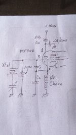
This is a very simple crystal oscillator you can build to start playing. C1 and C2 values will depend on the frequency you want to make the circuit run, but for normal crystals 100pF is a good value. This will produce 1/4 to 1/2 RF wats. This will not harm anything and is suffient to irradiate RF levels to be listened in any short wave receiver. The trimmer in series with the xtal allow you to move its frequency about 3 or 4KHz.
RF has no more danger as DC if properly used. Even a hammer may become a gun.
This is a very simple crystal oscillator you can build to start playing. C1 and C2 values will depend on the frequency you want to make the circuit run, but for normal crystals 100pF is a good value. This will produce 1/4 to 1/2 RF wats. This will not harm anything and is suffient to irradiate RF levels to be listened in any short wave receiver. The trimmer in series with the xtal allow you to move its frequency about 3 or 4KHz.
Attachments
Last edited:
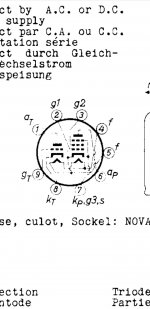
I forgot to mentionate you will need a 9VAC source to energize the heater. Below is the base pin assignment. The anode voltage can be obtained with a 24VAC source and using a doubler or tripler rectifier. A 24V source will give you about 70VDC with a doubler and a tripler about 110VDC. Both are more than sufficient for a first aproach.
Attachments
Ok, thank you... Looks like I will switch todays "movie evening" into "radio evening" to try to get some basic understandings about how radios work.Yes. Think as an open microwave oven. Microwave oven use much higher frequency (2450MHz vs 3.5MHz as we use in the "80mts ham band") but the risk is the same.
RF has no more danger as DC if properly used. Even a hammer may become a gun.
This is a very simple crystal oscillator you can build to start playing. C1 and C2 values will depend on the frequency you want to make the circuit run, but for normal crystals 100pF is a good value. This will produce 1/4 to 1/2 RF wats. This will not harm anything and is suffient to irradiate RF levels to be listened in any short wave receiver. The trimmer in series with the xtal allow you to move its frequency about 3 or 4KHz.
I like the oscillator idea. I will build it.
If I understand correctly, I can use 24vac and 3x greatz in series to get 110v?
For trimmer an air variable capacitor from old radio can be used, right?
Also RF choke can be used from old radio? Any values or measures for diy choke?
Can I use small xtal like this? Or are there any specs that I must follow? And it's frequency, what should be?

And finaly where would I connect antenna and audio signal (or does this circuit just trasmit fixed frequency tone)?
I'm sorry, I know that I'm asking some basic questions, I will learn to get the idea.
- Home
- Amplifiers
- Tubes / Valves
- Help me put these tubes into good use... I need a project