Question :
When i do an AC analyses what are the nodes to track?
Vout/Vsource? but this includes the input condioting circuit...
Vout/Vdiff non inverting node
More importantly to check nyquist stability?
PH Vout - Vsource? i guess not since input cond circuit is out of GFB-loop right?
PH Vout - Vdiff non inverting input? seems more logical
PH Vdiff inv input - Vdiff non inverting input? could also be because in the end the ph between those two must be tracked right?
But i would guess Vdiff inv input is same as Vout only smaller in amplitude (voltage divider for feedback)
It seems not the case in simulation
Edmond,
Could you send the microcap files?
By the way do you have the models of your trannies? I don't...
Question : what is the gain peak on the bode plot i allways have?
Hi Olivier,
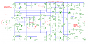
Here's the file of version-2 (remove .txt). I've also added a low distortion Baker clamp. THD20 is slightly increased from 7 to 7.2ppm. In Belgium this is called 'klein bier', isn't it? 😉
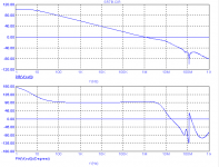
As for Bode plots, I prefer to look at the global NFB loop (by breaking the loop at the red cross). This kind of plot is more revealing about stability issues. The dip at 116MHz is due to the lead inductances of the output devices.
Regarding the gain peak in your plot, sorry, I don't know what caused it. Perhaps instability of the VAS. Just find out by trial and error (using different models etc.)
As for TMC vs TPC, TPC causes not only overshoot, but also slightly more distortion (8.5ppm). Please forget TPC, it's so outdated.
Cheers,
E.
Edit1: C3 & C4 improve the HF PSRR.
Edit2: In order to reduce the power dissipation in Q17/18, you might increase R22/26 to 68 Ohms and R24/25 to 470 Ohms.
Attachments

Last edited:
Thanks Edmond for the schematic it also includes the models ! 😎
I send you my schematic too, maybe you can check it out sometime...
I just ran an AC analyses on your circuit without touching anything. Your unity gain occurs at 10MHz while the phase shift is already -260°. The gain at -180° is still 13dB this is @ 5MHz. Is this stable?
Anyway who wants a -3dB HF rolloff starting @ over 800KHz ? Isn't that way too high? I would assume 160KHz more of something safe or do you reduce it later with extra input conditionning circuits?
Hm I will ask Mr Google about Baxandall
The only reason I can think of about the gain spike I get at around 100MHz is the presence of many 'poles' on the plot because they are related to the Q's (Cob's?) which are alll the same and in a simulation there is no spread in values so they all fall together. If I am right 'poles' in a bodeplot causes the gain to fall 20dB/decade. 2 poles would cause a further fall of 40dB/decade but at the position of the poles they will cause a gain peak before the rolloff starts. If there are 3, 4 or more poles very close to eachother they gain peak can be huge. I could also be very wrong and its just a Spice phenomena ... or something else ...
I will get rid of the TPC. You call it differently, where do the letters stand for? I see it looks like TPC but the resistor is routed to the output and not to the power rails.
You use a 100 Ohm resistor at the input, why? BV does it also.
See ya ...
Olivier
Ik ga een tas koffie halen ! You would say : Ik ga een bakje koffie halen
Attachments
Gee Edmond, your Circuit is realy complicated. I am having troubles understanding... by the way did you built this amp in real life yet?
I will do my best to understand 🙂
I will do my best to understand 🙂
Hi Olivier,Thanks Edmond for the schematic it also includes the models ! 😎
You're welcome.
I send you my schematic too, maybe you can check it out sometime...
Well, sometime, as I'm going to Crete in a couple of days.
I just ran an AC analyses on your circuit without touching anything. Your unity gain occurs at 10MHz while the phase shift is already -260°. The gain at -180° is still 13dB this is @ 5MHz. Is this stable?
That was the overall (and closed loop) response. This one says little about the stability. You have to look at the NFB loop, that is, break the loop where I've indicated (and take care of the DC operating point, for example, add one more NFB path that acts only at the DC level).
Anyway who wants a -3dB HF roll-off starting @ over 800KHz ? Isn't that way too high? I would assume 160KHz more of something safe or do you reduce it later with extra input conditioning circuits?
Indeed, 800kHz is a bit too high. Increasing C2 to say 1nF is one way, but not I'm not sure whether all pre-amps like this. Another way is to increase R2, but then you'll get slightly more noise, though probably 'klein bier'. And finally, Fc also depends on Zo of the pre-amp. Anyhow, a moot question.
Hm I will ask Mr Google about Baxandall
The only reason I can think of about the gain spike I get at around 100MHz is the presence of many 'poles' on the plot because they are related to the Q's (Cob's?) which are alll the same and in a simulation there is no spread in values so they all fall together. If I am right 'poles' in a bodeplot causes the gain to fall 20dB/decade. 2 poles would cause a further fall of 40dB/decade but at the position of the poles they will cause a gain peak before the rolloff starts. If there are 3, 4 or more poles very close to each other they gain peak can be huge. I could also be very wrong and its just a Spice phenomena ... or something else ...
I also think it's something like that. You can verify this by subsequently zeroing all the Cob's (CJC in spice) and see what happens.
I will get rid of the TPC. You call it differently, where do the letters stand for? I see it looks like TPC but the resistor is routed to the output and not to the power rails.
TMC stands for 'transitional Miller compensation' See also: http://www.diyaudio.com/forums/soli...terview-negative-feedback-75.html#post1167958
You use a 100 Ohm resistor at the input, why? BV does it also:
Just a matter of 'force of habit'.
See ya ...
Olivier
Ik ga een tas koffie halen ! You would say : Ik ga een bakje koffie halen
Ja, maar ik ga nu een grote pils halen in Hoppe.

E.
PS: Please pay attention to the max. allowably power dissipation and safe operating area (SOA) of the driver and output trannies.
Gee Edmond, your Circuit is realy complicated. I am having troubles understanding... by the way did you built this amp in real life yet?
I will do my best to understand 🙂
Don''t worry, it only looks complicated, but the principles are simple. The CMCL comprises Q13... Q18, the rest is just main stuff.
I've never built this amp, but the PGP amp (see syn08's or my website) is also stabilized by means of a CMCL and, as it seems, also Xdsl drivers from ADI, see: What's wrong with this picture? 🙂
So it really does work.
Cheers,
E.
Edmond,
I found out my circuit has a dramatic phase shift behavior! I barely get phase margin ... i could never find a way to improve it ! but now it seems like raising the diff amp degen resistors solves the problem ... too bad this reduces thd performance too :-(
and a lot
I found out my circuit has a dramatic phase shift behavior! I barely get phase margin ... i could never find a way to improve it ! but now it seems like raising the diff amp degen resistors solves the problem ... too bad this reduces thd performance too :-(
and a lot
Cmcl
After some thoughts (and some glasses of beer), this is plain **. Regarding the schematic in post 79, the only thing that really matters is good Vbe matching (and thermal coupling) between Q16/Q27 respectively Q15/Q28. My apologies for the confusion. IOW, the simpler version can be made as good as the the more complicated version.
............
The 1st version senses the VAS Iq indirectly by monitoring the collector currents of emitter followers (Q19/20). Although it does work, it's not that accurate, as Iq also depends on Vbe matching of emitter followers.
...............
After some thoughts (and some glasses of beer), this is plain **. Regarding the schematic in post 79, the only thing that really matters is good Vbe matching (and thermal coupling) between Q16/Q27 respectively Q15/Q28. My apologies for the confusion. IOW, the simpler version can be made as good as the the more complicated version.
Edmond,
I found out my circuit has a dramatic phase shift behavior! I barely get phase margin ... i could never find a way to improve it ! but now it seems like raising the diff amp degen resistors solves the problem ... too bad this reduces thd performance too :-(
and a lot
This is how I've assessed the global loop response; can't get wrong:
Attachments
Raising the diff amp degen resistors drop the OLG from 110dB to 90-95 dB
causing the thd to raise 5 to 10 x
causing the thd to raise 5 to 10 x
Edmond,
I found out my circuit has a dramatic phase shift behavior! I barely get phase margin ... i could never find a way to improve it ! but now it seems like raising the diff amp degen resistors solves the problem ... too bad this reduces thd performance too :-(
and a lot
Hi Olivier,
First, don't use that ****** TPC and you will see enough phase margin.
Furthermore, I've removed C6 and R14 and inserted a buffer (VCVS) between Vout and the NFB stuff. Please try the circuit below. ULGF = 925kHz and PM = 81 degrees.
Attachments
OK tonight I will check your MOD.
You really REALLY don't like TPC 🙂
I read about TMC on the forum ... quite a huge discussion but interesting.
I read also, Self does the same trick as Slone in his new release of his book!? But why I ask myself ... two 'doorgewinterde' specialists showing non functionnal circuits!? As an electrical engineer I am not electronics expert and even less in audio world. I wanted to build an amp all by myself no compromises in quality !! I buy a book (slone) and BANG I start off using Slones unworkable design. After years of search one becomes very suspicious and looking for answers in no good places I can tell you 🙂 bad house earthing, celphones, bad vibes in the house and worse 🙂
Till later...
Hi Olivier,
I've seen Self's circuit too, but I don't think he is that stupid, as he is well aware of the pitfalls of a complementary VAS:
"Also, as John Linsley Hood pointed out, the standing current through the bias generator is ill defined compared with the usual current source VAS" (Self D, EW+WW, Oct. 1993, p.822).
So I assume that his circuit was only meant as illustrative example of the very basics without digging into details. Nevertheless, it's disappointing that he didn't give any clue how to solve this problem. Probably because he simply doesn't like a complementary VAS. Moreover, he is totally focused on his simplistic blameless amp.
BTW, one more virtue of a CMCL: it also solves the 'fighting VAS' issue. See: http://www.diyaudio.com/forums/solid-state/110760-pgp-pretty-good-poweramp-8.html#post1338861
For another example of a CMCL + CFB input stage, see: http://www.diyaudio.com/forums/solid-state/110760-pgp-pretty-good-poweramp-19.html#post1408551
As for TPC, indeed, it's not my best friend. 😉
Cheers,
E.
Edmond, here i found someone claiming the Slone amp to work just fine ... I asked him to be sure ... it's even made on a standard pcb ...
Could this be true?
http://www.diyaudio.com/forums/solid-state/165100-randy-slone-passes-4.html
Could this be true?
http://www.diyaudio.com/forums/solid-state/165100-randy-slone-passes-4.html
Hi,
Yes it works perfectly fine and currently spent so many hours on fine tuning it.
I have assembled Slone's circuit of Figure11.12 on a general PCB but the BIAS/Vb multiplier was not stable. Though it worked fine but when i tried to adjust the voltage to 2.88V across Q19 it was not stable and once overshot and damaged my out and driver stage.
So to solve this problem all i did was to removed Q11 & Q12 and modified the circuit around Q13 & Q18 and it is PERFECT and very stable! I have Q19 on OP heat sink along with trim pot. I am using output Triples with feed forward circuit so the negative feedback has different values. It is stable with no oscillation and I can share video/photos what I have done so far, I am using MPSA42/92, TIP41/42 and MJ15003/4
I would say Slone’s topology is superb!
It turns on and off softly and no thumps at all, it sounds good to my ears better than Blameless.
Regards,
Smathias
Hi Smathias,
Do you have the schematic for us your working pcb? The one with stable Qbias.
If you read this thread all the way; what do you think about what we say? Do you think luck has anything to do with it or unluck for us 🙂
Sorry to be so suspicious but your project baffles me !! I spent thousands of euros already and years of frustration and you build it on a standard pcb with flying wires ... Or I am the unluckiest dude or I didn't understand crap of it and i must think selling my gear 🙂
Or you have all the luck? Or something else
enlight us please
psst be careful the specialists here are going to be very very critic 🙂
see ya
Edmond,
The remark you made about a little voltage on the diff inputs -> Iq VAS to fly away demotivates me a bit. I understand this means the circuit is just really crappy again and i'll find myself bbq'ing Q's again ! :-{
Sorry i have trouble understanding your setup .... input at fb node ... phase analyses with +360° (why do a full turn?).
a voltage dependant voltage ... ?
i suppose this is the clamp?
anyway i still continue studying
see you later
...
BTW, one more virtue of a CMCL: it also solves the 'fighting VAS' issue. See: http://www.diyaudio.com/forums/solid-state/110760-pgp-pretty-good-poweramp-8.html#post1338861
Yes, a common mode loop is certainly capable of that. It can also be used to dynamically bias a complementary differential VAS. I use a CCS to set the current for a differential bridge and the two complementary common mode loops provide steady bias. There are advantages to having a VAS that always uses a constant current. Aside from the excellent PSR, it is nice to have spot on steady bias generation for the OPS.🙂
- Home
- Amplifiers
- Solid State
- HEEEELLLPPP : M. Randy Slone Mirror Image Topology Construction - Troubles