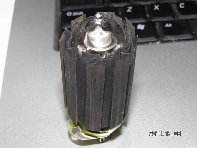
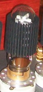
heatsink for a small tube
For which one?
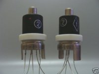
I have a pair of such thingies, to toy with them... Used as radar screen deflection tubes in military jets.
Attachments
Member
Joined 2009
Paid Member
If the glass stopped all the IR radiation, then closing the glass doors on a fireplace would stop the IR and would leave the human absorbers on the sofa cold. (at least initially) I think the glass on most tubes is thin enough to allow some significant IR transmission. You can feel the heat from the filament before the glass gets hot. (Try putting ones hands around a light bulb that is just turned on and see how fast they get warm!)
Imho the transparency of the glass to the spread of IR radiation from the plate is a red herring to the thermal design needed if one was focussing on cooling a power valve.
As an aside, unless the plate is cherry-red or heading for death then its infrared emission is moved to a lower frequency than that of the heater/cathode.
It is also difficult to differentiate between transparency and re-rediation of infrared radiation from a surface such as a valve envelop, and similarly for a fireplace cover or a light bulb (although these two examples progressively move the spread of radiated energy more to higher wavelengths where the transparency of glass is certainly increasing or reached max).
I think that Wavebourn's example heatsink that started the thread is a significant compromise and probably poorer than the Pearl examples - as the conductive cross-section from the contact metal to the outer 'fin' section is very minimal, and even the metal-glass contact would have a relatively high thermal interface resistance due to air-voids.
Ciao, Tim
I think that Wavebourn's example heatsink that started the thread is a significant compromise and probably poorer than the Pearl examples - as the conductive cross-section from the contact metal to the outer 'fin' section is very minimal, and even the metal-glass contact would have a relatively high thermal interface resistance due to air-voids.
I pulled them from some US Army equipment; I think engineers who designed them knew what they were doing.
Good reference information on opacity of valve envelope glass to plate thermal radiation is in this application note from a temperature sensor company:
http://ircon.com/web/pdf/an109.pdf
A good pictorial of the emission spectrum of a blackbody down at plate temperature is shown at:
HGH infrared - Infrared blackbody radiation
Glass is pretty much opaque at wavelengths longer than 5 micron, and a 230C (440F) blackbody has a peak response at 6 micron. So I'd be estimating at least 70-80% of the plates net energy transfer that goes via radiation to the glass envelope gets absorbed as heat.
Any radiation that made it through the glass and then got reflected back to the glass by some external surface would again get mostly absorbed by the glass.
Any radiated energy from a hot external surface, such as a fitted heatsink, that hit the glass would cerrtainly just get absorbed by the glass, as the emitting surface temperature would be relatively low.
But once we are on the outside of the glass envelope then for most normal situations the predominant heat transfer is going to be conduction from the glass into the surface air and then convection away from the tube. And anything that restricts that process (such as a shielding can) would end up causing a hotter glass envelope, and hence hotter internal parts.
Thanks for the links.
I just measured the thickness of the glass for a horizontal sweep power tube, and its the .027 inch figure used in figure 1 of the IRCON link. That would put it's transmissivity at the 70 to 75% level down to 4.2 microns. I think your figure of 230 C for the plate has to be too low, because that is the rating for the glass temp. I would expect a source with maybe 1/2 the area of the glass to be at least twice the temp of the glass (possibly more, ie, dull red glow, visible in darkness, starts around 475-500 C). In which case the glass IR transmission would be the major cooling channel.
C F Color
400 752 Red heat, visible in the dark
474 885 Red heat, visible in the twilight
525 975 Red heat, visible in the daylight
581 1077 Red heat, visible in the sunlight
700 1292 Dark red
800 1472 Dull cherry-red
900 1652 Cherry-red
1000 1832 Bright cherry-red
1100 2012 Orange-red
C= Centigrade
F= Farenheit
Last edited:
Yes, anodes themselves are cooled by radiation. But maximal power dissipation depends very much on convection.
Here is the graph attached: allowed power dissipation of GU-50 depending on air temperature, when glass envelope is 200 degrees Celsius. As you may see, in 100 degrees environment only about 15W is allowed, when in 20 degrees all 40 Watt.
Edit: can't attach the file, the link is not active. I'll add a link on the file on my site.
Here it is.
An externally hosted image should be here but it was not working when we last tested it.
Last edited:
Yes, but GU-50 has around twice the thickness of glass of most common tubes. So it will be absorbing much more IR in the glass. The tube socket for it looks like it used forced air cooling.
I did not mean tube type and power/temperature numbers; I meant dependence. The better the glass is cooled, the more power dissipated by anode allowed.
Yes the temperature of the plate would likely be hotter than 230C (440F), and I guess 'red heat, visible in dark and twilight' would be a likely upper range given that few would be normally operating their amps at 'visible in daylight' unless they've mis-calculated their bias levels, enjoy 100-110% design level bias, or a mad guitarist.
The other influences that get drawn in to a balanced view are the glass thickness, glass type, the spread of energy over the spectrum that is reaching the glass, the geometrical spread of energy that is leaving all the plate surface, and the level of external 'heatsinking'.
Your measurement for glass thickness puts the tranmittance at 4 micron wavelength at about 70%, dropping rapidly to a negligible level at 5 micron.
We can't really comment on glass type.
The spread of energy over the range of wavelengths is like a mathematical integration, but also needs to factor in how the energy of a photon changes with wavelenth (inversely).
The geometrical spread of temperature over the anode indicates that not all energy leaving the plate is at the nominal maximum temperature - which I think would typically be focussed on the 'central' region of the plate sides for a beam pentode.
The external heatsinking performance will influence the plate temperature - the better the heatsinking then the lower the anode temperature. Sort of like phase-change specticles!
Given all the balancing factors I'm still viewing the majority of energy will be absorbed.
Ciao, Tim
I guess Wavebourn's graph presents the design centre recommended power dissipation levels for free air ambient, and as Wavebourn indicates the 200C constant glass temperature would equate to a 'constant' anode temperature (or temperatures of internals that the manufacturer was happy to let the tube operate at).
The equipment designer would then need to interpret how the local amplifier environment would impact - eg. forced air cooling would allow a higher ambient; whereas nearby valves and heat sources and free air-flow obstructions would work the other way.
The equipment designer would then need to interpret how the local amplifier environment would impact - eg. forced air cooling would allow a higher ambient; whereas nearby valves and heat sources and free air-flow obstructions would work the other way.
I guess Wavebourn's graph presents the design centre recommended power dissipation levels for free air ambient,
Yes.
But the question was, does heatsink help to cool down anodes, or not.
Imho the answer is yes, as is based on a simple thermal resistance concept and the fundamental mechanism of blackbody radiation between two surfaces in a vacuum.
If the anode has energy being pumped in to it, similar to the semiconductor die, then its equilibrium temperature is related directly to the thermal resistance between it and ambient, and the temperature of the ambient. We could simply think of 'ambient' as the internal surface temperature of the glass envelope, and the glass could be assumed to be 100% opaque to the net power radiated from anode to glass. The thermal resistance is then the radiation interface in a vacuum.
For a certain shape outline of anode and glass, the plate will reach an equilibrium temperature that allows the anode energy to transfer via radiation to the glass. If the shape outline doesn't change, or the blackbody characteristics of the plate or glass, then if you don't change the energy going in to the anode, but reduce the constant glass temperature then the anode temperaure decrease, and vice-versa.
The effective thermal resistance from plate to glass (Rpg to coin a new parameter in the datasheets) would likely be non-linear due to all the competing influences of glass transmission and absolute temperatures of surfaces.
Of course the other more practical part of the answer is about the performance of the heatsink on the external side of the glass envelope.
Yes.
But the question was, does heatsink help to cool down anodes, or not.
Yes. If the heatsink is an efficient one and a true blackbody absorber with no heat reflected back and able to create a temperature gradient, then Prevost's Exchange principle would apply. The larger the gradient, the better the transfer.
On other hand, if the heat sink blocks off air circulation and is not able to carry the heat away or reflects the heat back, then it would be useless.
Read little about black body radiation for more details.
Even though you stand by the army or some company doing a good job of designing that heatsink, I suggest that without a datasheet or some other confirmation of performance, you may not get the benefit you are hoping for.
If you have a good eye for 'cherry red' then you could do a comparison, but that would probably need a hole drilled through the heatsink!
If you have a good eye for 'cherry red' then you could do a comparison, but that would probably need a hole drilled through the heatsink!
The better the glass is cooled, the more power dissipated by anode allowed.
Very weak dependence imho. To improve heat transfer some glass tubes like GU72 have anode contact on top. That design allows anode heat be taken away from glass envelope by thermal conductance not by IR radiation only. Here we can put good radiator on top that would work efficiently.
Cooling glass envelope by itself does not make big sense for anode cooling. Like it was mentioned earlier in the topic tube screening with metal radiators could protect other parts in proximity.
imho for audio gear small footprint not very critical so in a proper design tubes could be placed in a right way they do not need any additional parts to function properly.
- Home
- Amplifiers
- Tubes / Valves
- Heatsinks for tubes?