Michi124 said:Hi Anthony,
I have added my needs to the parts wiki
(after finding out about the trafos that are included).
Please let me know your paypal-email for a quick payment.
Thanks for this nice opportunity!
Duely noted.
The Parts Kit GB for Kari's X-BOSOZ is now closed. Please ensure you are paid by the 15th of June or your order will be cancelled.
Many thanks to all those who participated early on this offering, IMHO you are getting a fantastic value for the money. I am sure everyone will be more than satisfied with the parts selection for the kits.
DIYCLUB Biz has confirmed delivery of the transformers from the factory to them is 3 weeks. Surface shiping to me will be about 6 weeks. For those of you who just bought the Preamp Kits, you can expect delivery in 4 to 6 weeks from today. I will gladly ship partials to those who want them, but you will pay for shipping twice, including two sets of packaging.
Local Pick ups and a cup of tea are always welcome.
Regards
Anthony
Anthony,
What is your plan on volume control? And input selector (manual or electronic)? We want something nice, right?
What is your plan on volume control? And input selector (manual or electronic)? We want something nice, right?
fcel said:Anthony,
What is your plan on volume control? And input selector (manual or electronic)? We want something nice, right?
Well I ordered myself a full balanced Remote enabled, processor controlled Relay fitted with Holco resistors unit for $210US from DIYClub Biz.
Here is the unit:
http://eshop.diyclub.biz/product_info.php?cPath=85_186&products_id=218
V-03 (Holco) balance US$210.00
Remote volume control board, full balance design (four pieces of volume control board) using relay switching two sets of resistors (R-2R network).
1dB per step, attenuate from 0 db to -80dB, output. Holco resistor, with four channel relay input select and CPU control display,
dual mono design, left and right channel can be fine adjustment.
Each set consist four pieces of resistor volume relay and input relay board
one piece of display board
two pieces of power regulator board
one remote handset
Member
Joined 2002
Coulomb said:
Well I ordered myself a full balanced Remote enabled, processor controlled Relay fitted with Holco resistors unit for $210US from DIYClub Biz.
Here is the unit:
http://eshop.diyclub.biz/product_info.php?cPath=85_186&products_id=218
V-03 (Holco) balance US$210.00
Remote volume control board, full balance design (four pieces of volume control board) using relay switching two sets of resistors (R-2R network).
1dB per step, attenuate from 0 db to -80dB, output. Holco resistor, with four channel relay input select and CPU control display,
dual mono design, left and right channel can be fine adjustment.
Each set consist four pieces of resistor volume relay and input relay board
one piece of display board
two pieces of power regulator board
one remote handset
I 2 was thinking about buying one of these. : O )
I have asked for a price break down on multiple units, maybe a Dozen, of the V03 Volume Controls. This is just a convenience for the handfull of people who are interested in getting one with thier Kit.
I will post a note if I think it is worthwhile and members of the parts GB can Pay Pal me the funds if they are interested.
Regards
Anthony
I will post a note if I think it is worthwhile and members of the parts GB can Pay Pal me the funds if they are interested.
Regards
Anthony
V-03 looks like something that Harvadian manuf. for a while back a couple years ago and which you have built. How did it work it - the Harvadian one? In your opinion, which one is less complicated to built and have a greater chance of success - V-03 or Harvadian?
fcel said:V-03 looks like something that Harvadian manuf. for a while back a couple years ago and which you have built. How did it work it - the Harvadian one? In your opinion, which one is less complicated to built and have a greater chance of success - V-03 or Harvadian?
The APOX works very well, a little quirky, the programming could have been cleaned up a bit. I had to build it myself as opposed to the V03 is a complete product.
Also Apox was $350US complete I believe and no longer available. Kind of makes the choice a little self evident.
Regards
Anthony
Kari said:Here's the schematics for the preamp it self.
/Kari
Here is the schematic for the amp. It was posted in the early pages. I do not remember seeing power supply for the unit, but you could figure out what is needed based on this one.
Hmm funny me. My previous post would be really iritating without this one, wouldn't be? Here is the link - this tread, post # 34:
http://www.diyaudio.com/forums/showthread.php?s=&threadid=53396&perpage=20&pagenumber=2
http://www.diyaudio.com/forums/showthread.php?s=&threadid=53396&perpage=20&pagenumber=2
Re: power supplies again
I am slow today. My previous posts are to help Lgreen.
lgreen said:
what about 10.75VAC for the negative part????
I mean if someone has a schematic with actual voltage and component values I would not need to ask these basic questions. Oooops. sorry for bringing that up again...
I am slow today. My previous posts are to help Lgreen.
more confusion
Ok, I don't know whats going on here but everyone is contradicting each other.
For example, Post #92 shows heatsinks for 5 MOSFETs. here.
Yet post #390 shows a link to post #34 that shows a schematic that has only 3 MOSFETs that I can see.
Here.
Moreover, Post #114 says that the PS is +60 and -9 V. Yet Columb in Post #374 implies that the pos. secondary is still 60V which would be an 80V supply. Then post #380 says -9 and +60 again.
I guess I can accept that the supplies are now confirmed at +60 and -9, but what about the MOSFETs? The schematic from #34 does not appear to match the board layout in #92.
Basically we have a free-for-all where people are trying to order parts and no well defined schematic or layout.
Re: more confusion
Well I ordered the GB parts from Kari's BOM that he posted and I spent a good deal of time clarifing Form, Fit and Function with him.
As for as the POST regulator rails, they have always been -9/+60, the AC Primary has always been 60VAC and 12 to 18VAC. I am not sure why anyone would be confused about this.
Reagrds
Anthony
lgreen said:Ok, I don't know whats going on here but everyone is contradicting each other.
For example, Post #92 shows heatsinks for 5 MOSFETs. here.
Yet post #390 shows a link to post #34 that shows a schematic that has only 3 MOSFETs that I can see.
Here.
Moreover, Post #114 says that the PS is +60 and -9 V. Yet Columb in Post #374 implies that the pos. secondary is still 60V which would be an 80V supply. Then post #380 says -9 and +60 again.
I guess I can accept that the supplies are now confirmed at +60 and -9, but what about the MOSFETs? The schematic from #34 does not appear to match the board layout in #92.
Basically we have a free-for-all where people are trying to order parts and no well defined schematic or layout.
Well I ordered the GB parts from Kari's BOM that he posted and I spent a good deal of time clarifing Form, Fit and Function with him.
As for as the POST regulator rails, they have always been -9/+60, the AC Primary has always been 60VAC and 12 to 18VAC. I am not sure why anyone would be confused about this.
Reagrds
Anthony
igreen,
2 of the TO220 packages are voltage references.
But i would also like to see a schematic for the actual version of the preamp including the voltage references and the difference between the cascoded and uncascoded setup.
illusionxx
2 of the TO220 packages are voltage references.
But i would also like to see a schematic for the actual version of the preamp including the voltage references and the difference between the cascoded and uncascoded setup.
illusionxx
illusionxx said:igreen,
2 of the TO220 packages are voltage references.
But i would also like to see a schematic for the actual version of the preamp including the voltage references and the difference between the cascoded and uncascoded setup.
illusionxx
The voltage references are to-92 packages and do-35(ish) packages. The "extra" pair of TO-220 devices are the cascode mosfets.
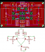
I believe the final version of the board was around post 134 - http://www.diyaudio.com/forums/attachment.php?s=&postid=638685&stamp=1115671858 It is a simple circuit, and you can almost see the schematic looking at the board, it is easy to trace out. The top FET and parts around it is the current source, the bottom pair the gain devices and the upper pair are the cascodes. Keep a copy of the original BOSOZ handy to help understand it. Kari's BOM states what you delete to eliminate the cascode.
I agree with a comment above. Could someone please post the "final" version of the schematic as committed on the GB board w/parts from that GB as well? High lighting the cascoded and non-cascoded option would be great!
It would really help settle some confusion, it's better than having everyone reverse engineer the schematic from the GB boards they ordered.
The lastest available schematic does not match the GB boards.
Kari we might need your help here.
Thanks,
-David
It would really help settle some confusion, it's better than having everyone reverse engineer the schematic from the GB boards they ordered.
The lastest available schematic does not match the GB boards.
Kari we might need your help here.
Thanks,
-David
Attachments
igreen,
2 of the TO220 packages are voltage references.
The voltage references are to-92 packages and do-35(ish) packages. The "extra" pair of TO-220 devices are the cascode mosfets.
Huh??? I see the board has labels Q1-Q5, looking like MOSFETs in TO-220 packages that are heatsunk, and REF1 and REF2 looking like voltage references that are not heatsunk. I see a schematic that lacks labels corresponding to the layout and lacks voltage references of any kind, and has only 3 MOSFETs.
I don't mean to be a pain I'm sure somthing accurate will be coming at some point, or I'll just have to get the boards and reverse engineer the schematic.
Hello, for the members of the parts group buy, I am undecided about the rectifier diodes. Should I go with an MUR415 Axial or an MUR815 TO-220?
As kari's PSU board does not provide for heatsinks for the rectifier diodes, (not really required), an axial device would suffice. The two diodes are identical Ultra Fast type devices. The Axial is 4 Amp rated and the the TO-220 8 Amp rated. In this application there would be no performance difference between the two devices. The difference is in the pricing, I could use the savings to boost component performance elsewhere.
I myself will be using FRED's a much more expensive Rectifier than the MUR type device, as much as $3 per device in place of $0.70 per device. FRED's are only available in a TO-220 package.
Here is a link for the MUR415.
http://rocky.digikey.com/WebLib/On-Semi/Web Data/MUR405,10,15,20,40,60.pdf
Here is a link for the MUR815
http://rocky.digikey.com/WebLib/On-Semi/Web Data/MUR805,10,15,20,40,60.pdf
Here is a link for the FRED I am referring to, for those interested.
http://www.irf.com/product-info/datasheets/data/hfa08tb60.pdf
Regards
Anthony
Use the axials if it will save some $$. The preamp won;t be drawing much current anyway, and I think there are more important places to spend the money.
I would agree with Brian. The power supply on the preamp is not the most critical. Yet it is certianly worth consideration. I think it would be nice to lay out where corners were cut for costs and how they could be improved, for those who would choose to.
I myself would probably just cough up the extra money for the FREDS now, but this being a group buy, I realise that I am probably in the minority.
Dave
I myself would probably just cough up the extra money for the FREDS now, but this being a group buy, I realise that I am probably in the minority.
Dave
- Status
- Not open for further replies.
- Home
- Amplifiers
- Pass Labs
- Heatsinks for Bosoz?