Hi and thanks for the input. The inductances are mesured and the llc is simulated so I feel pretty confident that the freq is not too low. I haveheating at idle where both inductances are i series and normally problems with too low freq are associated wtih heavy load and shorting out the transformer inductances.
I measured some more and I'm pretty sure its is not "classic" crossconduction.
My understanding is as follows: (please correct me)
This is an resonant LLC network and operating near the resonance means that the HB-switchnode swings high and low before the appropriate mosfet switches.
This is (as I understand it) the definition of ZVS (zero voltage switching).
This is normally detected by a short negative puls on the gate before turnon ( because the source is actually at a lower voltage than the drain).
I see that negative puls very clear and thus we have ZVS.
I dont think we can have cross-conduction and ZVS at the same time. For ZVS to work there has to be some dead-time.
So what is then causing the heat?
I connected and 15mOhm shunt between the low-side source and gnd.
The voltage across the shunt is equal to the current in the lower mosfet and I see some (very, very) short pulses of 2V across the shunt. Thats a very, very high current.
I tried googling the subject (H-brigde, crossconduction, shoottrough and such) and found descriptions of similiar pulses simply caused by the internal capacitances of the mosfet being discharged. As the HB-midpoint swings very fast in an LLC, I sort of understand that these discharge-current can get pretty big, but i dont understand why they would heat up the mosfet?
Hope my ramblings make sense. Greatfull for the help so far. keep it comming
Kind regards TroelsM
And the body diode of the mosfets? do give sometimes problems, or the circulating current of transformer, smps are sometimes complicated.
AN-9067 Datasheet(PDF) - Fairchild Semiconductor, Analysis of MOSFET Failure Modes in LLC Resonant Converter
Good point about the body-diodes. Will have to look into that.
I just tried disconnecting everything from the HB-switchnode and now the mosfets are only connected to the driver, - and they STILL heat up. Waveforms still look good, but ofcause its not ZVS any longer as the LLC is disconncted.
Will read the PDF. Thanks!
Kind regards TroelsM
I just tried disconnecting everything from the HB-switchnode and now the mosfets are only connected to the driver, - and they STILL heat up. Waveforms still look good, but ofcause its not ZVS any longer as the LLC is disconncted.
Will read the PDF. Thanks!
Kind regards TroelsM
Did you look at the output signal of the mosfets? is the square nicely?. maybe a to slow body diode, tried a other type of mosfet ? because then you now, is the transformer oke, do it not saturate or need it maybe a gap or not.
Some oscillations maybe, like extensive rining because of induction of board? much possibilities.
regards
Some oscillations maybe, like extensive rining because of induction of board? much possibilities.
regards
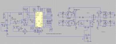
I have a project on the board of a smps for a hybrid amp output 2 x 120 volts 300 mA, 1 x 15 volts 5 amps, 2 x 65 volts 15 amps. I use a program for the calculations.
here some more doc,s,
(PDF) Optimal design methodology for LLC resonant converter
here some more doc,s,
(PDF) Optimal design methodology for LLC resonant converter
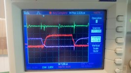
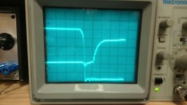
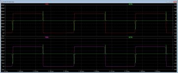
A few waveforms; yellow: voldtage over 15mohn shunt in series with lowside source, red diff-signal G-S topside mosfet, purple G-S lowside mosfet. Dead time looks ok, but still massive current spikes.
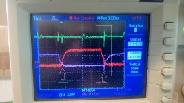
I see that risetime can better? not fast enough gate discharge? in deadtime left I think I see still shoot through? mosfet not completely off.
What you use for driver ic? need some amps drive power when using high Nc mosfets.
See pic, not mosfet completely off when switching give some overshoot.
Attachments
Last edited:
Yes, rise and fall times could be faster, but if the gate voltage falls below cuttoff before the orther turns on we should be good? Faster rise and fall may result in lower (transition) conduction loss, but it should not be a problem with Cdv/dt problem? Hope it makes sense
The gate signals exhibit small miller steps, so I assume there is no ZVS actually. And this could explain your excessive heating very well.Yes, rise and fall times could be faster, but if the gate voltage falls below cuttoff before the orther turns on we should be good? Faster rise and fall may result in lower (transition) conduction loss, but it should not be a problem with Cdv/dt problem? Hope it makes sense
To control this, you should show Vds vs Vgs of one MOSFET, lo-side for instance.
Instead prolonging dead-time, you will increase primary magnetizing current to achieve ZVS. This is done by increasing the gap between the ferrite transformer core halves.
I once tested an LLC converter with transformer disconnected.
The MOSFETs ran hot, due to the missing magnetizing current that normally charges output capacitance during dead-time. Connected with the gapped xformer, the MOSFETs stayed cold.
For that reason all my LLC-converters have a significant core gap.
Last edited:
I thought that a small dip in gate voltage before turnon was the sure sign of ZVS?The gate signals exhibit small miller steps, so I assume there is no ZVS actually. .
No, ZVS means turn-on without any miller effect.I thought that a small dip in gate voltage before turnon was the sure sign of ZVS?
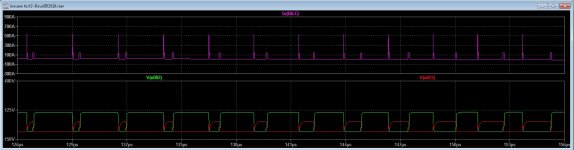
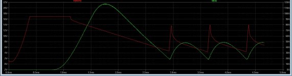
I have here a sim of a fase shifted inverter for welding 160 amps. here you can see clearly the pulses where the gate switch transitions happens, these caps get charged by circulating current and discharge, however a LLC is better for ZVS on all times the fase shift is only from a sudden power output.
This inverter is a own design making use of information from internet.
regards
This inverter is a own design making use of information from internet.
regards
Attachments
Last edited:
Before turnon gate voltage is about -8V, rising to +9V. My LLC operates with fixed frequency (=primary series resonant fq) and fixed duty cycle close to 50%. Considering these prerequisites the gate is driven ac-coupled using a coupling capacitor resulting in an ac gate signal.I understand the timing, but why dont the gate-voltage dip below zero before turnon?
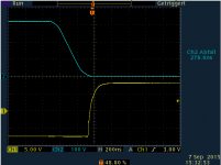
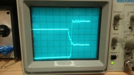
HB switchnode and lowside gate with llc connected. Vcc 70Vdc. Gate is 5V/div. Switchnode is 10v/div. 200nS/div (good old tektronix 2225, 50Mhz.
ZVS yes?
Kind regards TroelsM
Looks like true ZVS during turn-on, maybe there is another problem
- Status
- This old topic is closed. If you want to reopen this topic, contact a moderator using the "Report Post" button.
- Home
- Amplifiers
- Power Supplies
- Heating in LLC HB mosfets ?