Hey guys just wondering if someone has
A suggestion on how best to connect the heater wires (thick red wires) coming from the transformer and going to the tube socket. I was thinking to keep the run short and connect the the first stage tube 6sn7 on the bottom. Another option would be to run to the last power tube (top
 ).
).
A suggestion on how best to connect the heater wires (thick red wires) coming from the transformer and going to the tube socket. I was thinking to keep the run short and connect the the first stage tube 6sn7 on the bottom. Another option would be to run to the last power tube (top
Twist them all the way along like in other pictures in this thread, and run it as close to the chassis as possible.
Best to run them directly to the closest power tube, then daisy chain from there.
Twist tightly, and keep the twisted wires against the chassis, and away from the
input stage and all grids.
Twist tightly, and keep the twisted wires against the chassis, and away from the
input stage and all grids.
Thanks for the suggestions.
So better to run to the power tubes and have the run longer?
I'd have to run it to the last power tube socket (top) because there's no way to fit 3 wires in the tube socket pins.
So better to run to the power tubes and have the run longer?
I'd have to run it to the last power tube socket (top) because there's no way to fit 3 wires in the tube socket pins.
So basically I'm asking if it's best to hook up the red heater wires to the first tube 6sn7 and keep the run short or hook them up to the last tube (kt-120) and have the run long. Because of the thickness of the wires and the size of the holes in the pins i can't fit more than 2 wires in any one hole.
Hopefully someone chimes in. I'd like connect on the weekend.
Hopefully someone chimes in. I'd like connect on the weekend.
Ideally the KT120 should have been the tube closest to to the transformer.
Its filament current is about three times the filament current of the 6SN7.
Its filament current is about three times the filament current of the 6SN7.
Unfortunately I can't do much about that.Ideally the KT120 should have been the tube closest to to the transformer.
Its filament current is about three times the filament current of the 6SN7.
I suppose my question is isn't straightforward to answer.
Given the length of the filament wires, I'd twist and connect them directly to the KT120.Unfortunately I can't do much about that.
I suppose my question is isn't straightforward to answer.
Then also tie-wrap the transformer leads to the other twisted pairs to keep them in place.
Ok. Thanks for the advice.Given the length of the filament wires, I'd twist and connect them directly to the KT120.
Then also tie-wrap the transformer leads to the other twisted pairs to keep them in place.

Hello.
If I have 6 valves (5x600mA and 1x2,5A), is it okay to run a twisted pair from each socket to heater PSU (DC supply)? That would allow me to experiment with different PSUs later.
Runing a single pair daisy chained leaves me with less options.
I recently completed a SET amp with 4 - 6.3v tubes, I used a terminal strip off the PT 6.3v and ran directly to each tube socket.
Amp is based on a Blueglow video build where he ran the heater wiring this way.
If you have a test bed with multiple permutations of heater supply, then the guidance for heater wiring is hard to apply.If I have 6 valves (5x600mA and 1x2,5A), is it okay to run a twisted pair from each socket to heater PSU (DC supply)? That would allow me to experiment with different PSUs later.
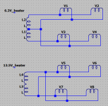
I am building an amp that uses 4 x 6.3v heater tubes that also have 13.5v heater equivalents (E/PCL86), and I'd like to make it possible to reconfigure it for the cheaper tubes. I have tried to solve this by having 2 * 6.3v heaters in two parallel tracks, ending in two pairs of 2 * screw connectors. My transformer is 8-0-8 3.2A, so I have to add a bit of resistance to support both types. Either one half of the heater supply supply one parallel pair, or the whole heater winding supplies two parallel pairs in parallel (should be clearer in the diagram).
If this is not a testbed, then I think it is prudent not to defer some of the more fundamental decisions. The heater wiring does make a difference, and once it is done, it is hard to get at it again and change it if you are working point-to-point.
Attachments
Yes, of course. Separate TP wiring for each tube is more cumbersome, but always a good option.If I have 6 valves (5x600mA and 1x2,5A), is it okay to run a twisted pair from each socket to heater PSU (DC supply)?
I am wondering about using Belden 8450 shielded twisted pair wire for my tube heaters? It is 22awg solid core wire with a foil shield, solid drain wire but an unknown twist ratio. I would use it to carry 1.25A at 6.3VDC about 18" would be the longest length.
Any thoughts?
Data Sheet
Any thoughts?
Data Sheet
If one follows the rules with twisted pairs, then there is no problem with hum from heaters. In very sensitive situations then DC is preferred. What would be the benefit? Or is it to use up some spare cable?
I have the cable and
it is already twisted and shielded. I am supplying DC for this phono-stage.
I thought shielding in addition to twisting might be good insurance.
it is already twisted and shielded. I am supplying DC for this phono-stage.
I thought shielding in addition to twisting might be good insurance.
I have the cable and
it is already twisted and shielded. I am supplying DC for this phono-stage.
I thought shielding in addition to twisting might be good insurance.
No further comments?
I suppose if you run the heaters with +/- DC (e.g., -3.15V and +3.15V to get a total DC voltage of 6.3V) then the shield could be at ground (or lifted if desired) and that would be the quietest way to run the heaters.
If the heater supply is single-ended, (e.g., 6.3VDC and 0V) then I'm not sure what benefit there would be from connecting the 0V end to ground potential or lifted ground, with the shield connected to chassis at one end of the heater cabling (and left open at the other) -- but I don't think that would hurt anything.
However, I've never tried this, so I don't know from experience. Just trying to puzzle it out as a thought experiment.
Thanks!I suppose if you run the heaters with +/- DC (e.g., -3.15V and +3.15V to get a total DC voltage of 6.3V) then the shield could be at ground (or lifted if desired) and that would be the quietest way to run the heaters.
If the heater supply is single-ended, (e.g., 6.3VDC and 0V) then I'm not sure what benefit there would be from connecting the 0V end to ground potential or lifted ground, with the shield connected to chassis at one end of the heater cabling (and left open at the other) -- but I don't think that would hurt anything.
However, I've never tried this, so I don't know from experience. Just trying to puzzle it out as a thought experiment.
- Home
- Amplifiers
- Tubes / Valves
- Heater Wiring - the Good the Bad and the Ugly