Thank you, The picture start to get clearer.
I was confused by the L of twisted wire vs straight parallel wires.
I tought that I was making the field stronger and wider.
But I have read a lot of cable papers and it start to make sense.
Thank you for your time.
I was confused by the L of twisted wire vs straight parallel wires.
I tought that I was making the field stronger and wider.
But I have read a lot of cable papers and it start to make sense.
Thank you for your time.
Member
Joined 2009
Paid Member
Putting the wires in the corner of the chassis also reduces the electric field.
I assume this works best when the chassis is steel rather than aluminium ?
Three Wires?
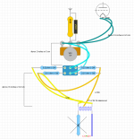
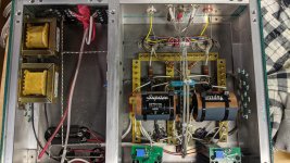
I'm wondering what to do about a heater circuit where one needs to run 3 wires? I'm modifying a 300B amp SET amp to allow both 300b's with their 5V heaters and the 300b's with 2.5V heaters (JJ2A3-40 for instance). The switch that will be used to select the voltage needs to have all three wires from the Hammond 166MS run to it - the two wires carrying the 5V and the one center tapped wire with 2.5V. The distance is 2.5 inches or so. Should all three be twisted together or is there a different suggestion? The wire off of the transformer is of poor quality when it comes to creating a tight twist as compared to teflon coated solid core stuff. The relationship between the parts before any modification is shown in the photo. I plan on the switch being located between the transformer and the hum-pot.
I'm wondering what to do about a heater circuit where one needs to run 3 wires? I'm modifying a 300B amp SET amp to allow both 300b's with their 5V heaters and the 300b's with 2.5V heaters (JJ2A3-40 for instance). The switch that will be used to select the voltage needs to have all three wires from the Hammond 166MS run to it - the two wires carrying the 5V and the one center tapped wire with 2.5V. The distance is 2.5 inches or so. Should all three be twisted together or is there a different suggestion? The wire off of the transformer is of poor quality when it comes to creating a tight twist as compared to teflon coated solid core stuff. The relationship between the parts before any modification is shown in the photo. I plan on the switch being located between the transformer and the hum-pot.
Attachments
Hello,
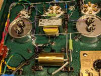
For the two heater supplies ( each coming from a Rod Coleman circuit) of the VT25A tubes i managed to guide the cables close to the copper chassis.
In the center of the 2 UX4 sockets there will be a noval socket for the E80cc/6085 input tube. Because there is a wire running close to the chassis coming from the power supply all the way to the noval socket to have a proper ground connecting for the parts attached to the noval socket i cannot put the 6,3 volt twisted wire close to the chassis ( top plate)
So i decided to let it run across the bottom plate untill it reaches the noval socket and then bend it make it go vertically up to the socket. Now i used a ptfe tube for '' guiding '' the twisted wire. It would be easy for me to make a copper bar or hollow tube firmly attached to the chassis to guide the twisted wire all the way to the socket. Would this be a good idea?? A tube will surround the wires completely. A bar would more give the idea of the wires being closer to the chassis. Any ideas on this?? Thanks a lot. Greetings, eduard
Attachments
Imho, the above two posts may or may not relate to any measureable hum ingress - indicating that measuring the hum level in the amp, and then making layout changes and remeasuring the hum level, is the better approach to take. It may be that no hum is measureable with even the most basic heater layout precautions, or that measured hum comes from other causes than heater wiring (which need to be managed first and foremost).
It may be better to initially construct an amp in such a way that wiring and layout can be easily modified, as well as allow hum related tests to be made easily (eg. allow a battery to power the heaters, and include a humdinger pot).
It is human nature to try and make the initial layout and construction perfect, only to then have to pull bits and pieces apart to fix something.
Hello,
I expect the two Rod Coleman regulators to work perfectly and they cannot be used with a humdigger pot.
The 6,3 volt 0,6A could! be a problem. The only way to '' approach '' the noval socket without coming to close to any sensual parts is the way i did it.
Just like to know if letting the twisted wire running through a copper tube which is firmly attached to the copper chassis could be an advantage? If it could it will be much easier to get such a tube and use it right away. I always read that one should start with the heater wiring.
Greetings, Eduard
With regards to twisting, I have started using the 317 voltage regulator with a soft start, (I have started this as our supply system is 230v -6/+10%, so the electric supply company can supply you anything between 220 and 250 volts, although I have never seen it out of the range of 245 and 250v around the country), thus always having the exact heater voltage, and not having a possible peak switch on voltage to prolong the filament life. Q, I do twist the wires to keep them together and tidy, but not as tight, as dc does not vibrate, like ac, and eliminates any possible hum, is slightly twisting the right thing to do !
Last edited:
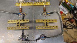
I ran my twisted heater wiring through some tinned copper braid when I needed to reach sockets in the middle of a phonostage build. I grounded one end of each section. Not the neatest job but there is no hum that is detectable.
Attachments
Hi ,AC for heater sound is better,dynamic ,bass,etc....but have some digital device,streaming device,router,switch in home,AC it will absort some EMI noise,
Are you agree?
Are you agree?
AC can be very good. Have you considered filtering your AC supply using chokes? Although this could be used to trim the available Voltage, it can also remove higher frequency problems.
Maybe it has been discussed before in this thread but I am too lazy to read everything. Anyway, in my limited experience I have seen and still see sometimes quite expensive tube equipment with hum problems.
Often the build quality is questionable but what I do see often is audio GND connected to the metal casing and not even use the PE connection (even when a PE IEC Socket is used!). It completely beats me why anyone would do such a thing but it is more common than one would think. I classify such equipment as unsafe despite the price tag. It also leads to dubious experiments with "ground wires" to get the stuff quiet. Why people /companies do not adhere to decade old safety regulations and why do these devices pass any quality check? In general tube DIY is one of the worst areas in DIY audio with regards to build quality and safety probably because stuff is large and accessible to many.
Especially tube stuff that carries high voltages should have the metal casing ALWAYS connected to PE for safety. One may connect audio GND lifted to PE. When done like this hum is not an issue. When I get the reply that homes in area X don't have PE well PE is out there for a lifetime 🙂 Even if this would be true one can have PE applied by a certified electrician or one better buys low voltage stuff.
Last edited:
@jean-paul by PE you mean protective earth? I'm taking it you mean the earth in the mains L-N-E.
Last edited by a moderator:
What's the best way to supply heaters for a 19v, 300mA tube like the PL33?
- DC floating
- DC with the negative side grounded, if so where and how?
- AC with a centre tap connected to ground (again, where and how?)
Bias voltage is only around 4v. a-k around 160v, 15-30mA current.
- DC floating
- DC with the negative side grounded, if so where and how?
- AC with a centre tap connected to ground (again, where and how?)
Bias voltage is only around 4v. a-k around 160v, 15-30mA current.
Hello guys - I am new here - building a KT88 SE amp. Re heaters - why not shield them like a coaxial cable - ground on one end - and avoid most of the induction noise? - Also - anybody knows what I should do with pin 9 's' on the ecc85?
See post no. 150.
Its the way I'll be doing the heater wiring in my parallel SE KT77 amp.
You can tightly twist wires using an electric drill.
Its the way I'll be doing the heater wiring in my parallel SE KT77 amp.
You can tightly twist wires using an electric drill.
andyjevans AFAIK heaters should never be floating, they should always be referenced to ground. Just connect your DC supply to ground. The best way to stopAC heater hum is with a humbucker, EG a 250r - 500r WW pot, wiper to gnd or elevated.
OferB, see - The Valve Wizard
Andy.
OferB, see - The Valve Wizard
Andy.
no element inside the tube should be left hanging not connecting to anything, i think this is the basic rule...
- Home
- Amplifiers
- Tubes / Valves
- Heater Wiring - the Good the Bad and the Ugly