I use centre-tapped winding, rectify it using Shottky pair, and stabilize for small tubes. Output tubes are powered by AC, with one end grounded, as the result.
...or current flowing from the rectifier to the cap through the same ground with signal. Why some people prefer vacuum rectifiers, because they have high resistance and such errors don't cause audible hum.However, it would be good to know what caused the buzz. Strange buzz/hum problems are often a symptom of parasitic oscillation.
Would this be possible even when the rectifier and the smoothing capacitors are grounded at a different point than the rest of the circuit? This seemed to cause the least noise when I was trying different grounding schemes.
Just wondering about the lower picture from the Valvewizard site, if I only have one heater winding and I'm powering two or more heaters, is the artificial center tap referenced to only one of the cathodes or what? So would the best implementation be that I run the twisted pair from the transformer to one of the tube bases, put the center tap resistors between heater pins and the cathode, and then run another twisted pair to the other tube bases in a daisy chain fashion?
Just wondering about the lower picture from the Valvewizard site, if I only have one heater winding and I'm powering two or more heaters, is the artificial center tap referenced to only one of the cathodes or what? So would the best implementation be that I run the twisted pair from the transformer to one of the tube bases, put the center tap resistors between heater pins and the cathode, and then run another twisted pair to the other tube bases in a daisy chain fashion?
Attachments
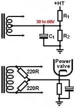
A heater circuit can only have one voltage reference. It doesn't matter too much what it is. If ground gives hum, try the cathode of an output stage.
Isn't hum induced via cross talk inside the pt?
Were a different pt featuring dedicated windings used, would hum be favorable?
How are secondary windings wound independent of each other to optimize rejecting hum crosstalk?
Or is hum stemming from massive current (four bottles power, five or seven bottles preamp, plenty massive current)
Were a different pt featuring dedicated windings used, would hum be favorable?
How are secondary windings wound independent of each other to optimize rejecting hum crosstalk?
Or is hum stemming from massive current (four bottles power, five or seven bottles preamp, plenty massive current)
Hum is 50/60Hz AC. It is there in the secondary - that is what the secondary is there for. Heater wiring can cause hum via capacitive coupling, magnetic coupling or heater-cathode leakage. DC elevation helps reduce the last one (or just buy good quality valves). Good wiring practice reduces the first two.
Buzz can come from crosstalk inside the power transformer. AC grounding the heater wiring can reduce this.
Buzz can come from crosstalk inside the power transformer. AC grounding the heater wiring can reduce this.
Agree, massive heater draw of current has impact directly on hum noise, the equations revealing the propensity of it by way of a dimensionless representation of magnitude will be a power relational to amperes, and likely copper topology and mass (worse with heavy gauge)
Just repaired a friends 2A3 amp which failed prematurely; the output tubes were out. The cause too high mains voltage on the direct heaters. I checked this whilst in the UK and by chance found his 230V AC rated transformer actually running at the correct 230V AC voltage; but a minute later the supply rose to a wopping 248V. The 2A3 requires 2.5V so the ratio at 230V is easily determined, which makes it 8% over the limit at 248V, the heater running at 2.7V.Agree, massive heater draw of current has impact directly on hum noise.......................
Anyone else had longevity issues with a 'wildly' high mains voltage ? Some parts in the UK has a shocking variation.
richy
utility power company line excursions
you're suppose to incorporate those MOV (metal oxide varistor?) protectors that blow shorts to the circuit breaker in the bldg, but at least surge is arrested before feeding amp vitals
you're suppose to incorporate those MOV (metal oxide varistor?) protectors that blow shorts to the circuit breaker in the bldg, but at least surge is arrested before feeding amp vitals
It isn't a surge when the 248V sits there for hours and gradually burns the emitters out ! The only solution is a constant volt transformer or go to indirect heating. This must also happen in the US; the line goes way out of operational spec.
utility power excursions revisited
tight tolerances on voltages can't be controlled in whopping reactive currents occurring in the grid proximity.
recall the industrial area (e.g. big shipyard) with huge current transients resulting from manuvering heavy loads "on and off" (like welding), or supershore power support onto naval submarines ported.
but if you're not in such area(s) of high industrial current draws and stoppages, then you need to squeak noise to the power company (their infrastructure may be slightly injured thus compromised tolerance on voltage.
those heavy heavy transformers used to stabilized in-house line voltage (either global or local transformer) cost bucks! but they do regulate as you replied, must be sized according to load size of draw
The cheapest way: regulated DC filament.
Pro: stable and safe filament voltage.
Cons: separated filament transformers and raw supplies, regulators.
Not so cheapest way: mains conditioner.
Pro: stable and safe filament voltage.
Cons: separated filament transformers and raw supplies, regulators.
Not so cheapest way: mains conditioner.
Living in the UK 30 yrs ago.....we never had these issues; it was always a rock steady supply voltage. Now I noticed the many substation transformers that have been radically downsized when the land is filling up with populations ! (doesn't quite make sense)tight tolerances on voltages can't be controlled in whopping reactive currents occurring in the grid proximity. <snip>
r:-
I would like to present my first attempt at heater wiring. I have tried to implement all I have learned from this thread. It is for the silent arts D-LA2A. I found that adding a little heat shrink was great at preventing the insulation from melting everywhere. Any tips on how to improve would be very welcome.
Attachments
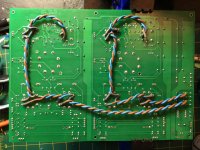
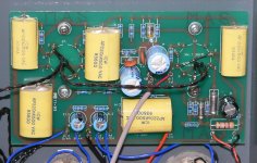
I would make the wires longer so that they can be placed parallel to the PCB at about an inch or so. That way you can avoid any accidental close coupling from a single wire a PCB trace where they cross. The wires then come away from the valve bases vertically. I use the technique in amplifier and it is completely silent at mains frequency. My photo shows the wires above the components on the other side of the PCB, but the principle is the same.
Attachments
I was hoping to squeeze it into a 2U case. If I can't and it has to go into a 3U case I might redo as you suggest. I guess I should test it first and see how it performs like it is. However I still have the transformers to up save for, which might take a couple of months.
What about using THIS on Filaments at the tube socket ?
Lets say its a 12AX7, AC heated.
How about using a RF Hash Choke right at the filament pins on the tube socket ?
I am thinking something like a J.W. Miller / Bourns 5200 Series, specifically, their # 5256-RC Hash Choke??
It is rated 500 mHY at 0.26 Ohms DCR and has a 2 A. current rating, sells for as little as $1.16 on line.
Any thoughts, comments or discussion of this, as an idea?? Pros, Cons ?
Thanks in advance.
Jeff
My goodness, an error, its 500 uHY, which is 1/2 a mHY. But THAT is the precise part and value / spec I wanted to discuss, located times two, on the tube socket pins, carefully orientated. Comments anyone ??
Thanks.
Jeff
Thanks.
Jeff
Hello !!
Neither a receiver or a transmitter.
Application is a DHT 3 Watt triode Loftin White type amplifier.
It uses a high mu input tube ( eg: 1/2 a 12AX7, 6SL7 or 12BZ7 ) direct coupled to something like a JJ 2A3-40 Finals tube. Powers ALTEC VOTT A7-800s.
Thanks in advance.
Jeff
Neither a receiver or a transmitter.
Application is a DHT 3 Watt triode Loftin White type amplifier.
It uses a high mu input tube ( eg: 1/2 a 12AX7, 6SL7 or 12BZ7 ) direct coupled to something like a JJ 2A3-40 Finals tube. Powers ALTEC VOTT A7-800s.
Thanks in advance.
Jeff
- Home
- Amplifiers
- Tubes / Valves
- Heater Wiring - the Good the Bad and the Ugly