Solid cores are better for heaters as the wires stay where you put them. Screened twisted pair cables almost certainly don't have a tight enough twist to deal with the magnetic field. Stick to the tried and tested method: solid core, tightly twisted, no need for a screen if done properly.
Shielded cable
Thanks DF I thought the shield would suppress the field almost to zero if grounded but if that's how it's always been done who am I to break tradition
Thanks DF I thought the shield would suppress the field almost to zero if grounded but if that's how it's always been done who am I to break tradition
The shield will suppress the electric field but not stop the magnetic field. A heater winding CT or humdinger pot will also deal with the electric field. Tight twisting reduces both fields for anything which is further away than the twist length, hence a tight twist is needed.
Miswiring heaters is unlikely to blow 450V caps.
12AX7 and some other twin triodes (but not all) have heaters which involve pins 4, 5 and 9.
12AX7 and some other twin triodes (but not all) have heaters which involve pins 4, 5 and 9.
Miswiring heaters is unlikely to blow 450V caps.
They might have been connected to AC?
I suppose anything is possible! Would 6.3V AC blow a 450V electrolytic?
Remote debugging when we don't know what he did, and probably he doesn't know what he did, is not easy.
Remote debugging when we don't know what he did, and probably he doesn't know what he did, is not easy.
I suppose anything is possible! Would 6.3V AC blow a 450V electrolytic?
Remote debugging when we don't know what he did, and probably he doesn't know what he did, is not easy.
I don't know the specifics of the amp in question, but if mis-wiring the 6.3V AC also took out the rectifier for the HT, either by a direct short or through some other component breakdown, then the caps might see high voltage AC... for a short while...
Low voltage AC could do the damage but I'd expect it to take longer.
That won't work. Most B9A valves have the heater on pins 4 and 5, but some double triodes have a different arrangement involving pin 9 too. For these, such as 12AX7, you connect 4 and 5 together, then wire the heater supply to 4/5 and 9. Or you can use 12.6V on 4 and 5, ignoring pin 9.gkenne said:connecting pins 4 & 5 of the EL84 to pins 4 & 5 of the 12AX7s,

Could be a sign of spurious RF oscillation getting propagated along the heater wiring, rather than normal hum.
Could be a sign of spurious RF oscillation getting propagated along the heater wiring, rather than normal hum.
Not RF, looked at it on a scope. I first tried a 100 ohm balance pot and it worked but still had a little residual hum, using the caps no hum. I also tried connecting the caps with clip leads across different tubes and the result was the same. If it was some spurious pickup the results would have varied moving the clip leads around. Perhaps someone else can try it and see if they get the same results. I first used Illinois Capacitor coupling capacitors and the results were the same, I only went to ceramic caps because they are physically smaller.
Attachments
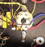
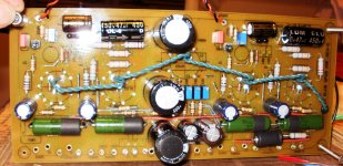
I've found that on filament windings with no center tap bypassing both sides of the filament line with caps works better to eliminate hum than a balance pot. I used .47uf @ 100V ceramic caps.
Hello
Thank you very much.
Great idea, I hope these work for the higher power GU50 to.. That is 12.6V but I must have to check the tube data.
I have 12.5V DC also. Is not better if I use DC for the GU50.
Again I have to take a look at the tube data what is the recommendation. Great help, thanks one more time.😉
Greetings Gabor
Looking for somebody who have AC heater with 300B and NO noise.
It could be possible as WE91 is ac ?
Thanks for your help.
Gilles.
It could be possible as WE91 is ac ?
Thanks for your help.
Gilles.
No noise??
Hi Gilles.
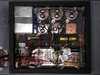
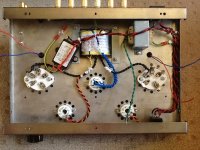
I'm getting 3.9mv and 2.9mv 100hz respectively at the terminals of my AC supplied JELabs 300B monoblocks. Nothing fancy here, just AC straight to a wirewound dropping resistor, routed around the outside and with a hum pot. I haven't tweaked it for optimum performance, just made sure the wires were twisted and placed to the outer edge of the chassis. Would be interesting to see what other folks are achieving and what measurement would be considered "No noise". (Now I've measured it I'm going to have to find out why I've got 1 mv difference. Damn!!)
Hi Gilles.
I'm getting 3.9mv and 2.9mv 100hz respectively at the terminals of my AC supplied JELabs 300B monoblocks. Nothing fancy here, just AC straight to a wirewound dropping resistor, routed around the outside and with a hum pot. I haven't tweaked it for optimum performance, just made sure the wires were twisted and placed to the outer edge of the chassis. Would be interesting to see what other folks are achieving and what measurement would be considered "No noise". (Now I've measured it I'm going to have to find out why I've got 1 mv difference. Damn!!)
Attachments
To echo valve5425's question, and out of my own curiosity, would 4mV of AC hum on the filaments of a 2A3 or 300B be considered objectionable?
--
--
I've found that on filament windings with no center tap bypassing both sides of the filament line with caps works better to eliminate hum than a balance pot. I used .47uf @ 100V ceramic caps.
If you wanted to use cathode bias on a DHT, but still use those .47uF bypassing caps for the filaments, where would you put the cathode bias resistor?
--
If you wanted to use cathode bias on a DHT, but still use those .47uF bypassing caps for the filaments, where would you put the cathode bias resistor?
--
I should think you would just connect the resistor from filament to ground. But then the .47 caps would act like a bypass and boost at very high frequencies. I'm only familiar with DHT power output tubes and on a power tube you would want a decent value bypass cap. Might be best to use a separate filament transformer in such a case.
Hi Gilles.
I'm getting 3.9mv and 2.9mv 100hz respectively at the terminals of my AC supplied JELabs 300B monoblocks. Nothing fancy here, just AC straight to a wirewound dropping resistor, routed around the outside and with a hum pot. I haven't tweaked it for optimum performance, just made sure the wires were twisted and placed to the outer edge of the chassis. Would be interesting to see what other folks are achieving and what measurement would be considered "No noise". (Now I've measured it I'm going to have to find out why I've got 1 mv difference. Damn!!)
hi
The differences may be due to the tubes. The 100Hz stems from harmonic distortion from cathode to anode. The distortion may differ, hence the amplitude of 100Hz. I wrote a bit more about this here:
http://tentlabs.com/Components/Tubeamp/Tubefilament/assets/Heatingmethods.pdf
The amount of DC shift wen driving the tube a bit harder is also an indicator of the 300b linearity, see:
http://ken-gilbert.com/images/pdf/2 non linear stages.pdf
best,
Guido
- Home
- Amplifiers
- Tubes / Valves
- Heater Wiring - the Good the Bad and the Ugly