....lol... Don't trust John's document
The yellow highligh J2, J4, J5 are totally wrong.
Heater: 12v
12SL7' - V1 and V2 - J1 and J3 (parallel)
6BL7 - V3 and V4 - J5 (series)
6BL7' - V1 and V2 - J2 (series)
12SL7' - V3 and V4 - J4 and J6 (parallel)
I think all the tubes in his doc would work fine. As long you put in the tubes, check H+ and H- to be at 12v. Different voltage mean wrong jumpers.
....lol... Don't trust John's document
Well, that's heartening... What should I trust? How did you figure this all out, emailing him?
Heater: 12v
12SL7' - V1 and V2 - J1 and J3 (parallel)
6BL7 - V3 and V4 - J5 (series)
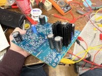
This is what I'm running. The 6BL7's are getting quite hot though. I got 12.0V across H+/H-.
Where can I measure heater current draw? Across those jumpers only got me ~2.3mA, and in series with either of the AC input connections got me ~3mA.
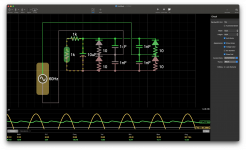
The amp is working, for what that's worth. I'm getting a clean amplified sine wave output on my scope.
Even his latest document still has wrong parts, label, and missing value. He used to answer emails 2 years ago but not lately.
I did trace every single point on the PCB and compare to his doc to make sure it's correct.
I really don't know how to check current draw
I think the tubes hotter in the preamp than in the amp.
I did trace every single point on the PCB and compare to his doc to make sure it's correct.
I really don't know how to check current draw
I think the tubes hotter in the preamp than in the amp.
Awesome… lol. Well, thank you for helping me sort things out. So J5 is the correct jumper for the 6BL7’s in V3/V4 then?
Yeah. Look at post #33 on page 2
If tube is 6.3v, you want to set series
If tube is 12v, you want in parallel
If tube is 6.3v, you want to set series
If tube is 12v, you want in parallel
You can run another output C3=10uF and R11=1M for sub out.
Check out the schematic from John
https://tubecad.com/2018/03/blog0415.htm
Check out the schematic from John
https://tubecad.com/2018/03/blog0415.htm
I don’t see where he references a sub out in that link. How does C3=10uF produce a sub out?
I have thought about making a sub out, since I do use a sub in my setup. Ideally I’d sum the channels and apply a low-pass filter.
I have thought about making a sub out, since I do use a sub in my setup. Ideally I’d sum the channels and apply a low-pass filter.
There was in another of his manual that he mentioned about it but I couldn't find where it's at. I did buy the 10uF but haven't tried out yet. I have seen someone in here has it.
What regulator and heatsink are you running? My kit came with an LD1085 and this massive heatsink. It's the single largest component on the board after the tubes, and is the limiting factor on case height. I'd like to fit something shorter if I can, but I don't want to under-size it.
Attachments
Same LD1085. I think he said either 2" or 2.5". I bought 2.5" when I was thinking 3" case. So with 1/4" spacing on top, my heatsink ends up right at the cover.
About the capacitor: lower value capacitor would set a low frequency cutoff 80Hz. Higher value, 5Hz for full range.
About the capacitor: lower value capacitor would set a low frequency cutoff 80Hz. Higher value, 5Hz for full range.
Ok, I have the 2.5” one. I mounted the tubes on top and the caps and heatsink on the bottom, so I can mount board to the underside of the top panel and let the tubes poke up through the top. That’s adds a bit of necessary case space… I’ll have to see what I can do, it’ll probably just end up being kinda tall. Maybe I can dismount the regulator and hook it up with some wire and mount the heatsink horizontally. I did that on my power amp build.
For the caps: Ok, so it’s a high-pass filter for the speakers when using subs. Gotcha. That makes sense. I remember reading about that in the context of his capacitor switcher board. I plan multiple revisions of this preamp project. I definitely want to add a low-pass sub output at some point.
For the caps: Ok, so it’s a high-pass filter for the speakers when using subs. Gotcha. That makes sense. I remember reading about that in the context of his capacitor switcher board. I plan multiple revisions of this preamp project. I definitely want to add a low-pass sub output at some point.
I took old cable box for the chassis but turned out the steel chassis gave a loud hum with PT. The only way to get away the hum was I had to raise the PT 5" high with wood and 4" away from the tube. So I save this case for E/L core PT for another project. Currently working on aluminum chassis for this where aluminum doesn't have hum problem with Toroidal Core


Very nice, thanks for the pictures! My plan is to build a case with wood and brass plates. The kit I got was filled-out by a member on here with the toroids. I'll see how they work. I have pots for them coming from China, so I'll see if that makes a difference. If not, I've been looking at some Hammond E/L core, and they aren't expensive.
I'm setting it up in a temporary case for now, so I can play with it while I build the chassis. I'll send you pictures later once it's done. I think you'll enjoy 😉
I'm setting it up in a temporary case for now, so I can play with it while I build the chassis. I'll send you pictures later once it's done. I think you'll enjoy 😉
Put the toroids 2" from the pcb behind the PS, then you're fine. That's where it doesn't encounter the hum. No on right/left side of the tubes. So you're looking like 6x12. I am going for 8x12 wood, and aluminum on top for pcb. I think toroid has magnetic all around so it causes hum with steel chassis.
If you're looking for e/l core, my suggestion is going for 280vAC or 300vAC 120mA, and 6.3vAC/4A, I would refer 300vAC so I can have big R12 to reduce AC ripple without using choke.
I used RJ45 network wires for input/output, no hum problem.
If you're looking for e/l core, my suggestion is going for 280vAC or 300vAC 120mA, and 6.3vAC/4A, I would refer 300vAC so I can have big R12 to reduce AC ripple without using choke.
I used RJ45 network wires for input/output, no hum problem.
What do you think about putting the toroids on top of the case in pots, like traditional tube amps? I plan to experiment a bunch anyway.
I definitely plan to bump up the amps, either if I need to switch to e/l core, or if I measure >2A current draw on the heater circuit. Interesting idea to go high voltage on B+. Is the idea that the bigger R12, the lower the ripple, more or less, period?
I've got shielded microphone wire I plan to use for the final I/O setup. I figure that should work pretty well.
I did try on top too. Testing with steel chassis so i don't know about aluminum yet. However, I put PT on top of 2x4 then no hum. The best location is in the back. Shouldn't be problem with e/l core, I tried Edcor without problem. Big R12 will lower the ripple, 3k up is good.

Cool! Thank you for your diagrams. ****, thank you for all the help you've given over the past few days. I really appreciate it. I'll keep you informed as to my progress!
Won't increasing C7 smooth the ripple as well, without reducing B+ voltage?
Won't increasing C7 smooth the ripple as well, without reducing B+ voltage?
Not much different since you're using around 230v so 150uF is fine. It does reduce more after R17, then more at R12. That's good enough. You don't use B+ at first RC, so not concern.
- Home
- Amplifiers
- Tubes / Valves
- Heater power supply producing ~1/2 expected voltage - Aikido All-In-One line stage