OH fickig sh!t, your'e right that 2 D would create C.T....lol.....Actually, I show what the option 2 look like
If your PT has C.T., you only need 2 diodes on top.
John's document is the most confusing I have ever seen, wrong labels, and missing a lot of parts too.
If your PT has C.T., you only need 2 diodes on top.
John's document is the most confusing I have ever seen, wrong labels, and missing a lot of parts too.
Yeah, some of the diodes are mislabeled on the A and B sides of the board, too. Not really a “beginner” kit. Oh well, I’m sure I’ll figure it out eventually.
I’ll try the center tap arrangement again, now that I have a better sense of things. I’ve started a new thread for the heating/buzzing issues I’m getting with the HV transformer, as I think I’ve sorted out the hookup issues, thanks for this thread.
I’ll try the center tap arrangement again, now that I have a better sense of things. I’ve started a new thread for the heating/buzzing issues I’m getting with the HV transformer, as I think I’ve sorted out the hookup issues, thanks for this thread.
Read this if you wish. As I mentioned before, you may encounter hum as hell with TOROIDAL. The best way is place the PT far away from the tubes. sunil didn't have problem with E/I Core PT. Stay away from steel/metal chassis. Aluminum is better. If hum in one channel, it could be a bad/burn resistor. That's what happen to me.
https://www.diyaudio.com/community/...o-all-in-one-octal-acf-2-buffer.330985/page-5
https://www.diyaudio.com/community/...o-all-in-one-octal-acf-2-buffer.330985/page-5
Last edited:
I’ll give it a read. The hum is the transformer coil it’s self humming, not induced. And the heating is my bigger concern. It doesn’t stop increasing until I turn it off.
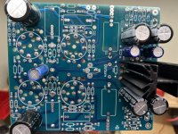
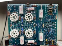
Can you take pictures both top and bottom, I can take a look at the traces. And keep the PT away from any metal when testing.
What are the value for C5, C8, and C7?
What are the value for C5, C8, and C7?
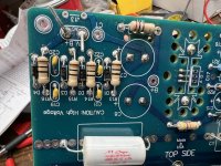
All yours Ds are correct
You should have C5, C7, C8 at 150uF to reduce AC ripple. Hope someone can give some suggestion on C7 and C8 if I am correct
C6 is better with 2.2uF or 10uF( I have 10uF)
I am not sure C13 and C14 are correct position.
Just estimate: assume 230vAC, B+ before R17 is around 314vDC then R17 200 r/3w would be around 300vDC. If you disconnect R17, you shouldn't get hum/hot on PT. It could be defect.
You can replace R17 with choke
Thanks for the review!
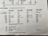
The manual suggests a value of 47uF to 300uF for C7 and C8, with suggested values or 47uF for 450V or 220uF for 20V.
For C6 I followed the suggested range of 0.1uF to 1uF. Why do you suggest higher? How did you select a value or 10uF?
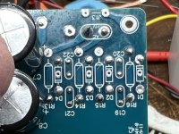
I think I found the cause of the hum. I think it was one of the filter capacitors in the bridge network (C19-C22). See my other thread for more details.
The manual suggests a value of 47uF to 300uF for C7 and C8, with suggested values or 47uF for 450V or 220uF for 20V.
For C6 I followed the suggested range of 0.1uF to 1uF. Why do you suggest higher? How did you select a value or 10uF?
I think I found the cause of the hum. I think it was one of the filter capacitors in the bridge network (C19-C22). See my other thread for more details.
C6: The higher the capacitance, the lower the noise null goes in frequency
R12 - 3k? That's too big, it would drop under 200vDC
47uF is for tube rectifier. For diodes, you can use 100-220uF/450v ...Use 400v-450v since you're at 250-300v
My suggestion R17 3w or 5w
R12 - 3k? That's too big, it would drop under 200vDC
47uF is for tube rectifier. For diodes, you can use 100-220uF/450v ...Use 400v-450v since you're at 250-300v
My suggestion R17 3w or 5w
I took my values from the attached table, considering I’ll be using 12sl7’s as my driver tubes.
I’ll have to go back and remember why I chose 0.22 for C6. Odd that I’d be off the opposite end from you.
What’s the tradeoff to increasing the size of C7/C8? Why not go even bigger? Or, why go smaller with a tube rectifier?
I’ll have to go back and remember why I chose 0.22 for C6. Odd that I’d be off the opposite end from you.
What’s the tradeoff to increasing the size of C7/C8? Why not go even bigger? Or, why go smaller with a tube rectifier?
Attachments
The C6 statement was from John and he told me use 10uF
47uf is the max for the tube rectifier.
No benefit to more than 220v. Most use 100uf or 150uF for preamp with diodes. And 220uf and up are big that won't fit on your pcb.
Check both C5 caps again, the top one in the image, look like pop out.
For 12sX7, you 're good at 120vDC, no need chock, Big R17 and R12 will reduce AC ripple.
C7 and C8 still need at least 350v rating.
Last edited:
For C6, the math is 159155/C6/R10, right? That gives me a -3dB point of ~9 Hz for my R10 of 82.5k, and ~0.2 Hz if I switched to 10uF. Seems good. Not sure how I chose 0.22uF.
I’ll up the values of C7,C8 then. Seems like a good call.
Rechecked both C5’s, they seem good.
I’m running 12SL7, not SX. Happy to boost R17 though, I have a 470R part on hand I could drop in. For R12, I was just following the guidance in the manual.
I’ll up the values of C7,C8 then. Seems like a good call.
Rechecked both C5’s, they seem good.
I’m running 12SL7, not SX. Happy to boost R17 though, I have a 470R part on hand I could drop in. For R12, I was just following the guidance in the manual.
12SL7 then need 250-300v.
With 230vAC, you probably has R17 100r/3-5w then R12 at 50-80r/3w to get around 250-280v. Since you need 40v drop with tubes.
C6 can be 4uF-10uF
Keep R10 and R9 as default. (82.5k and 100k)
Guide in the manual is way off. My 280vAC with 100r R17,, choke option (I used 440r instead), and 80r R12 to get 300v
Last edited:
So the goal is to get ~280V after R12? I have some more resistors I can play with. I can also order new C6, that’s not problem. Is there any reason to go lower rather than higher?
Without tubes, you want 340v after R12. If you have 300v, it will drop to 260v with tubes.
I think you can run from 200v-300v without problem.
You can test B+ after R12 first while order new one.
I think you can run from 200v-300v without problem.
You can test B+ after R12 first while order new one.

Ok, here's the test I've just run: With R17 swapped to 470R and R12 still at 3K, I'm getting ~306V from the end of R17 to G, and ~243V from the end of R12 to G. This is with 12SL7 in the driver stage and 6BL7 in the output stage (with the jumpers set for 6.3V to the output tubes). Is that a good test, or should I do something else?
243v after R12 without tubes? When you have tubes (load), you would lose from 35-45v. Change R12 to 1k probably gives you 20v more.
Look like a bad idea, doesn't have enough heater current.
12SL7: 12v - 0.15A --> 2 tubes: 0.3A
6BL7: 6.3v - 1.5A .--> 2 tubes: 3A . However, in series for 12v, the current may drop 1/2 as 1.5A. I don't have knowledge on this
Total : 3.3A or 1.8A
When 6.3vAC/4.16A ---> 12vDC/2.6A
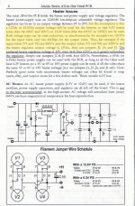
Be careful, don't get confuse about 12v and 6.3v, Your filament configuration is 12v, NOT 6.3v
12SL (12v) configure as Parallel (if you put in series, you need 24v) J1 & J3
6BL7 (6.3v) configure as Series to run at 12v , J5
Look like a bad idea, doesn't have enough heater current.
12SL7: 12v - 0.15A --> 2 tubes: 0.3A
6BL7: 6.3v - 1.5A .--> 2 tubes: 3A . However, in series for 12v, the current may drop 1/2 as 1.5A. I don't have knowledge on this
Total : 3.3A or 1.8A
When 6.3vAC/4.16A ---> 12vDC/2.6A
Be careful, don't get confuse about 12v and 6.3v, Your filament configuration is 12v, NOT 6.3v
12SL (12v) configure as Parallel (if you put in series, you need 24v) J1 & J3
6BL7 (6.3v) configure as Series to run at 12v , J5
Those voltage numbers are with tubes, sorry, I should have been more clear.
I followed the voltage guidelines on that attached scan. I believe I have configured the jumpers correctly for the 6BL7's to get 6.3v as the (top) output tubes and the 12SL7's to get 12.6v as the bottom driver tubes. J4 and J6 are disconnected.
Your current concerns are concerning, though. Assuming the voltage issues are sorted out, I should simply need to provide a larger transformer, right? Maybe adjust some resistor ratings?
Attachments
Last edited:
- Home
- Amplifiers
- Tubes / Valves
- Heater power supply producing ~1/2 expected voltage - Aikido All-In-One line stage