Here are a couple of mine, both Kevin Gilmore designs.
A Gilmore DynaFET (FET version of DynaHi), internal.


Mini Dynalo, mostly SMD, runs hot.


A Gilmore DynaFET (FET version of DynaHi), internal.
Mini Dynalo, mostly SMD, runs hot.

Similarly, a voltage amplifier for electrostatic headphones:All my projects are in this state. Here's a mini-zen ...
😀😀😀
Attachments

Yeah, military grade.
But yes, of all the amplifiers, it can withstand 24/360 operation.
During this time, two Stax amplifiers have already failed😀.
But yes, of all the amplifiers, it can withstand 24/360 operation.
During this time, two Stax amplifiers have already failed😀.
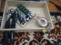
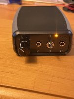
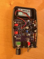
Here is a portable unit with 3 Meier cross-feed levels. I used SMD cross-feed components on the backside of the board near the DP4T switch. The buffer is a JFET-input CFP.
After using this for awhile I've learned that I don't need 3 crossfeed levels - just a high and a low would be fine for me.
jason
After using this for awhile I've learned that I don't need 3 crossfeed levels - just a high and a low would be fine for me.
jason
Attachments
@Pars you old devil! Showing off that Gilmore kit. That DynaFet is very rare beast, if you say it's his best, I'll believe you. I looked into building the balanced boards and the obsolete Fets would cost £300 alone, not even closely matched.
Got my balanced CFA2 (4 boards), and SMD Dynalo. Got boards and parts for the CFA3 balanced but not for now. Building DACs now...


Also have a Mini, so cute. Wish I had the case like yours, will likely get some end panels done for an existing case.
Got my balanced CFA2 (4 boards), and SMD Dynalo. Got boards and parts for the CFA3 balanced but not for now. Building DACs now...
Also have a Mini, so cute. Wish I had the case like yours, will likely get some end panels done for an existing case.
Last edited:
I would actually say that the CFA2/3 are his best sounding amps. I had built a 2ch CFA2, which was pretty close to the DynaFET (which is also 2 ch unbalanced), but the balanced CFA3 probably sounds a bit better. My phones are modified Fostex TR50P or Dan Clark Ether C Flow planars, which take some power to sound their best.
That is an interesting 4-pin XLR jack in your last photo. What is it?
That is an interesting 4-pin XLR jack in your last photo. What is it?
@Pars - Lemo connectors, from AliExpress. Really nice connectors, very recommended. Size 1B or 2B 4 pins is perfect for the front - locking, pull sleeve to release

These are plug and socket sets - https://www.aliexpress.com/item/100....order_list.order_list_main.29.296e1802CBE8X1
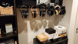
In this pic you can see two 3B Lemo connectors from DAC to Dynalo and 2B for headphone connector. Mogami quad Microphone cable.

These are plug and socket sets - https://www.aliexpress.com/item/100....order_list.order_list_main.29.296e1802CBE8X1
In this pic you can see two 3B Lemo connectors from DAC to Dynalo and 2B for headphone connector. Mogami quad Microphone cable.
Last edited:

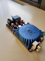
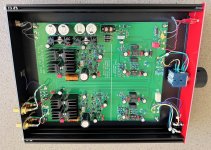
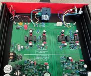
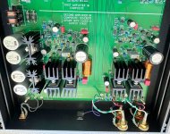
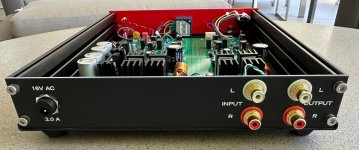
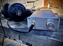
Here is ROJO, a headphone amp I finished just in time to display and demonstrate at the 2019 Burning Amp Festival. It's a composite amplifier, using an IC opamp (OPA1611 or AD817) first stage, and a class-A all discrete opamp second stage. Both opamps are enclosed in a single global feedback loop. The discrete opamp's output stage runs at 100mA of bias current, so it remains class-A up to 200mA of output current. There are four output transistors per channel, each one mounted on its own deep-fin heatsink.
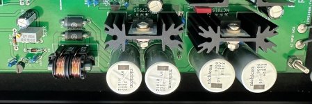
Power supply is an external AC wall wart feeding a pair of half wave rectifiers, one for negative and the other for positive. There are four voltage regulator ICs: +18, +15, -18, and -15. They're mounted in pairs (front and back) on two shallow-fin heatsinks. Right next to the silver Nichicon "BY" series filter capacitors. Raw rectified DC is regulated to 18V, and this 18V is fed thru a second regulator to provide very-regulated 15V which powers all amplifying circuits.
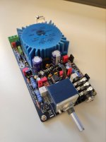
Next to the regulators there's a common mode choke to filter the incoming AC from the wall wart, and next to the choke there's a little circuit which controls the output relay ("muting relay") to prevent thumps at power-off and power-on events. The relay is a tiny beige box next to the headphone jack's flying wireleads near the front panel.
The front and rear panels are actually epoxy fiberglass printed circuit boards, which means the PCB fab does all the drilling and high precision silkscreen printing. Both panels are electrically connected to the chassis (you can even see the solder joints and the text "FARADAY CAGE") for electromagnetic shielding.
_
Power supply is an external AC wall wart feeding a pair of half wave rectifiers, one for negative and the other for positive. There are four voltage regulator ICs: +18, +15, -18, and -15. They're mounted in pairs (front and back) on two shallow-fin heatsinks. Right next to the silver Nichicon "BY" series filter capacitors. Raw rectified DC is regulated to 18V, and this 18V is fed thru a second regulator to provide very-regulated 15V which powers all amplifying circuits.
Next to the regulators there's a common mode choke to filter the incoming AC from the wall wart, and next to the choke there's a little circuit which controls the output relay ("muting relay") to prevent thumps at power-off and power-on events. The relay is a tiny beige box next to the headphone jack's flying wireleads near the front panel.
The front and rear panels are actually epoxy fiberglass printed circuit boards, which means the PCB fab does all the drilling and high precision silkscreen printing. Both panels are electrically connected to the chassis (you can even see the solder joints and the text "FARADAY CAGE") for electromagnetic shielding.
_
Attachments

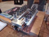
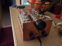
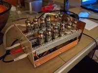
I was looking at the absolutely massive 100 Watt plus per channel OTL amplifier my friend Max had built and commented to Rene' Jager that it would be fun to build an OTL headphone amp, as that would be much more budget friendly. A few months later he showed up with this. I eventually convinced him to sell it to me. I have forgotten most of the details, but I believe it has four output tubes per channel. It's a lot of fun to have something that glows in my collection of gear.
Attachments
@Mark Johnson that is a lovely bit of design Mark, as always. Custom single boards to fit an enclosure is the way.
Will this be available to the masses at some point?
Will this be available to the masses at some point?
No, ROJO and AZUL are not planned for release.
diyAudio member Ti Kan took photos of them on display at the 2019 Burning Amp Festival
https://www.amb.org/ti/audio/burningamp2019/baf2019-18.jpg
https://www.amb.org/ti/audio/burningamp2019/baf2019-19.jpg
https://www.amb.org/ti/audio/burningamp2019/baf2019-20.jpg
https://www.amb.org/ti/audio/burningamp2019/baf2019-21.jpg

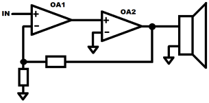
Curious about the schematic...DIY Headphone amp
Full transistors schematic
2w for 32 ohm load
Designed and made it in 2002. Class A. Gave it as a present to my brother.
- Home
- Amplifiers
- Headphone Systems
- Headphone Amp Photo Gallery