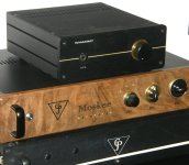
Some projects just lend themselves to extra effort. This is not complete, as I am waiting on a few more parts, but since the case was so nice to begin with, why not add brass? The DIY Audio case is excellent for enhancement. I want to add a brass disc for the headphone jack as well. Yah, I know, I am somewhat tempted to do the sides as well.
Attachments
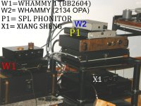
Given the right time/day a horse race is inevitable for me comparing equipment. Especially in this case, where two of the products are the same brand and model and the only real change is the op amp used in each. The other two amps are important not only for comparison, but as a sort of reference of where we are coming from to begin with. There are some complications that arise here, as the 4 unit are not hooked up entirely the same. The Xiang Sheng for example is the DAC being used to feed the two Whammy amps. The issue is that one of those outputs is tube and the other is SS. As much as this may considered a non starter, I was surprised at how little the differences were. Mostly in the top and the difference in actual output of each is very slightly different. That is one example of differences. In spite of that, the sound differences of each amp are mostly splitting hairs to me except for the Xiang Shang, whose sound is quite a bit brighter than any of the others.
Give me some time here, as I have only be able to set up for output levels of each amp and haven't done serious music listening. Um yah, at least one of these will be for sale. And yah know what? Another set of headphones for comparison would be benefit too. Let the games begin.
Give me some time here, as I have only be able to set up for output levels of each amp and haven't done serious music listening. Um yah, at least one of these will be for sale. And yah know what? Another set of headphones for comparison would be benefit too. Let the games begin.
Attachments
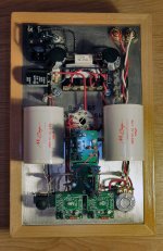
Here's my Frankenstein, somehow keeps blowing FETs that select power supply (transformer or battery powered), therefore I unsoldered battery because I needed full power today. The battery side has never been blown, only the mains PSU side kills the FETs, probably should get higher voltage ones).
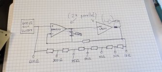
It's LL1517s driven with mixed feedback (negative impedance), into 2x parallel LME49600 impedance multiplier with impedance taps. No particular reason for all of this, just a case of "why not?".
It's LL1517s driven with mixed feedback (negative impedance), into 2x parallel LME49600 impedance multiplier with impedance taps. No particular reason for all of this, just a case of "why not?".
Attachments
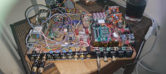

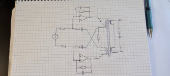
There's no complete schematic. I have attached the amplifier part. In actual build there's some changes, but the buffer part still consists of simple impedance multiplier. Then there's a lot of latching relays driven from Arduino to change modes, xrk971's SSR protection circuit for headphones out. The protection circuit was also copied for PSU selection. Mains PSU is using the Cap MX board I bought from you, battery power is 4s2p, so around +/-8v. Recently I bought HE6se v2, so had to test it with +/-17V from mains PSU. Mostly I use this "cutting board" when I need to test some circuits, as there's SE -> BAL / BAL -> SE conversion, so it's useful.
Attachments
Indeed a frankenstein! But i also see a lot of passion in it too. I bet it sounds pretty goodHere's my Frankenstein, somehow keeps blowing FETs that select power supply (transformer or battery powered), therefore I unsoldered battery because I needed full power today. The battery side has never been blown, only the mains PSU side kills the FETs, probably should get higher voltage ones).
It's LL1517s driven with mixed feedback (negative impedance), into 2x parallel LME49600 impedance multiplier with impedance taps. No particular reason for all of this, just a case of "why not?".
- Home
- Amplifiers
- Headphone Systems
- Headphone Amp Photo Gallery