Perhaps this will help:lumanauw said:...I still cannot figure out how to make 2 CFP to become current mirror. Can you suggest anything?
Attachments
Mikeb! In CFB input satge ,I used 10k CFBresistor.Result is noise ,.I replaced by 4.7k but still noise. Perhaps CFB is always more noise than a normal input stage. My current source is 1mA ,collectorresistor is 10k
to lumanauw:
Where to put the 2cfps ? into vas or diffamp ?
For a currentmirrored vas cfp does not help, but for asymetrical
R-loaded it helps.
If you put R-loads into the cm-vas, then the cfp helps.
CFP helps always if you have currentswings.
In the ckt posted to thanh, the cfp only lowers thd by factor 2,
because of the currentmirror at output of diffamp, so currentswing
is minimal. Without the currentmirror (R-loaded) and a buffer to vas
(or cascoded vas) the thd from diffamp is nearly nil. (harmonics below noise)
Fascinating way of using cfps, haven't thought at that !
Does this help ?
Your cfp-resistor is much too big, D.Self recommends 2.2k, i use 2k.
1k already does the job. Everything above 2k has minimal change,
but increases problems.
For 1k you should use at least 4ma ccs. 2ma with 2k is ok. (1ma per tail)
Maybe you should use higher currentsource and lower collectorresistor.
And don't forget emitterresistors. With all these changes noise
should have gone. If not, add a small RC-filter to the collectors
of the diffmap. (100pF+330ohm)
My amp also uses cfp in the inputstage, there's absolutely no noise
audible. I use 33ohm Re,2k for cfp, and 1k for Rc. Currentsource is 2ma. (now Rc=1.5k, i added a buffer to vas)
What is your supplyvoltage ? jfets don't like high voltages. (If you use jfets)
Mike
Where to put the 2cfps ? into vas or diffamp ?
For a currentmirrored vas cfp does not help, but for asymetrical
R-loaded it helps.
If you put R-loads into the cm-vas, then the cfp helps.
CFP helps always if you have currentswings.
In the ckt posted to thanh, the cfp only lowers thd by factor 2,
because of the currentmirror at output of diffamp, so currentswing
is minimal. Without the currentmirror (R-loaded) and a buffer to vas
(or cascoded vas) the thd from diffamp is nearly nil. (harmonics below noise)
Mr Evil said:
Perhaps this will help:
Fascinating way of using cfps, haven't thought at that !
Does this help ?
thanh said:Mikeb! In CFB input satge ,I used 10k CFBresistor.Result is noise ,.I replaced by 4.7k but still noise. Perhaps CFB is always more noise than a normal input stage. My current source is 1mA ,collectorresistor is 10k
Your cfp-resistor is much too big, D.Self recommends 2.2k, i use 2k.
1k already does the job. Everything above 2k has minimal change,
but increases problems.
For 1k you should use at least 4ma ccs. 2ma with 2k is ok. (1ma per tail)
Maybe you should use higher currentsource and lower collectorresistor.
And don't forget emitterresistors. With all these changes noise
should have gone. If not, add a small RC-filter to the collectors
of the diffmap. (100pF+330ohm)
My amp also uses cfp in the inputstage, there's absolutely no noise
audible. I use 33ohm Re,2k for cfp, and 1k for Rc. Currentsource is 2ma. (now Rc=1.5k, i added a buffer to vas)
What is your supplyvoltage ? jfets don't like high voltages. (If you use jfets)
Mike
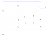
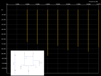
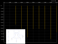
The increased effective beta will bring it closer to the ideal current mirror. It can be combined with other techniques (e.g. Wilson current mirror) to make it even better. Whether the benefit is worth the extra complexity or not I don't know, since I've never actually built an amp with such an arrangement in it, only simulations.MikeB said:...Fascinating way of using cfps, haven't thought at that !
Does this help ?..
You prompted me to do a direct comparison to isolate the effects.
I've attached graphs of FFT analysis showing an improvement in distortion; as expected, improved matching between input and output currents improves linearity. I also expected it to increase gain, but it didn't seem to affect it at all.
I've attached graphs of FFT analysis showing an improvement in distortion; as expected, improved matching between input and output currents improves linearity. I also expected it to increase gain, but it didn't seem to affect it at all.
Attachments
Hi, Mike,
I will put 2 cfp as current mirror in the place of VAS, so the VAS will have the same current as happened in one leg of differential---->VAS with no gain. Why? Because I wanted to use CFP differential, that already has enormous gain. So I wanted the VAS do not have gain, just current mirror from one leg of differential.
Are you saying that for my purpose like above, I dont need CFP for current mirror? Just ordinary current mirror will work fine?
Mr.Evil,
If we number the transistor from left to right 1-2-3-4, then in your drawing, the major current carrier is transistor no 1 and 4. But the one tied B-C is transistor no 2, which with no 3 is the minor current carrier. Will this whole arrangement works as good current mirror?
ckt ->circuit?In the ckt posted to thanh, the cfp only lowers thd by factor 2,
Do you mean that diff stage with resistorload has no harmonics ?because of the currentmirror at output of diffamp, so currentswing
is minimal. Without the currentmirror (R-loaded) and a buffer to vas
(or cascoded vas) the thd from diffamp is nearly nil. (harmonics below noise)
with or without?
My CFB resistor is 10k because I want a big gain -> a mount of feedback is big -> distortion is decreased by a large mount .
You don't like the big gain because you want a wide O/L BW, aren't you?
thanh said:ckt ->circuit?
Do you mean that diff stage with resistorload has no harmonics ?
with or without?
My CFB resistor is 10k because I want a big gain -> a mount of feedback is big -> distortion is decreased by a large mount .
You don't like the big gain because you want a wide O/L BW, aren't you?
Okay, i will use cct from now...
A diffstage with resistorload + cfp has nearly no harmonics. But only
if you don't put some strange load to it, so the buffer to vas.
Spice showed me that using cfp-resistors above 2k don't increase
gain much.
Sometimes it's better to lower gain, it can greatly increase linearity.
I had cases where the factor of lowering the gain was identical to
lowering harmonics. It's very simple to construct an amp without
real harmonics except the outputstage. At least you need all this
gain just to compensate the errors done by the very last stage.
I'm still looking for an easy way to solve this...
Then i will try a NoGlobalFeedbackTopology.
Of course, if you are looking for ultralow thd, you can achieve this
only with massive ol-gain. But this works only for lower freqs.
Decreasing gain and linearizing the cct gives also low thd for
higher freqs. My amp has now nearly the same amplitude for 2nd
and 3rd harmonics for 1khz and 20khz. I was not able to achieve
this with high gain.
The cct i've posted to you is a high OL-gain, having impressive low
thd @ 1khz. But for 20khz my lowgain amp has better performance.
So i will use this highgain-cct for a subwoofer amp.
Mike
My amp = cfb diffstage+ folded cascode + resistor load + darlington VAS + T-circuit output stage .A diffstage with resistorload + cfp has nearly no harmonics. But only
if you don't put some strange load to it, so the buffer to vas.
Does "so" mean "hence" ?so the buffer to vas
😀
How are these?My amp has now nearly the same amplitude for 2nd
and 3rd harmonics for 1khz and 20khz
thanh said:
My amp = cfb diffstage+ folded cascode + resistor load + darlington VAS + T-circuit output stage .
Does "so" mean "hence" ?
😀
How are these?
What is T-circuit ?
Darlingtonvas = buffered vas ?
Yep, i meant "hence"... 😀
The harmonics are ~ 120uV,70uV, 12volt swing into 4 ohms.
Not the lowest numbers, but it sounds very clean and smooth...
OLgain is about 1:55000 (95db), total gain 1:45 (33db), hence feedback of ~62db.
(if i do dezibel-calc right)
Mike
with cfb resistor 10k, the treble sound is very heavy and the bass sound is very low (easy to burn out output transistors). Generally the sound is very "real-time" .
with 4.7k and 10uF capacitor bypass the degeneration ,the treble sound is less heavier and I feel 2nd .But probadly I heard TIM
A year ago, my amp = current source 2mA +diff stage +3.3k collectorresistor +no folded cascode + darlington cascode VAS + T-ciruit output stage. In the sim, it is bad .In real world, it is bad too!
I tried with 1.2k collectorresistor and increase current source to the bias VAS is 3V. It is bad too! but my neighboorhood like it
T-circuit is EF type II at http://www.dself.dsl.pipex.com/ampins/dipa/dipa.htm
you go to "5.3 Distortion 3"
you go to "5.3 Distortion 3"
Hi, Mike,
What is your opinion on DestroyerX's Blameless amp experience? The Blameless amp he build, SIM very well indeed (very low distortion), but the sound is bad. What caused this?
I wanted to explore more about non feedback amp, especially with the use of Hawksford Error Correction for the final stage.
I asked about possibility of single differential for Non feedback amp http://www.diyaudio.com/forums/showthread.php?s=&threadid=40449.
What do you think, single differential is bad for non feedback power amp?
What is your opinion on DestroyerX's Blameless amp experience? The Blameless amp he build, SIM very well indeed (very low distortion), but the sound is bad. What caused this?
Yep, agreed.Sometimes it's better to lower gain, it can greatly increase linearity.
With low gain, you can get non-feedback topology. Charles Hansen makes a strong argument about non-feedback amp sound. He said the feedback never feels right, no matter how you do it.Then i will try a NoGlobalFeedbackTopology.
I wanted to explore more about non feedback amp, especially with the use of Hawksford Error Correction for the final stage.
I asked about possibility of single differential for Non feedback amp http://www.diyaudio.com/forums/showthread.php?s=&threadid=40449.
What do you think, single differential is bad for non feedback power amp?
Hi lumanauw !
If using NoGlobalFeedBack, i wouldn't use any diffamp...
As i once said, your topology from the thread "will this work..."
seems great for this. In sims it showed low harmonics before
outputstage. 2nd harmonic was ~2mv for 16volt swing, other harmonics
were far below ! But outputstage is the real problem for nonfeedback,
it added 50mv harmonics (2nd,3rd,4th,5th) to the signal, dampingfactor = ugly...
As the gain needs to be that low, bandwidth is automatically "far"
above normal audioband.
I think the "only" problem with nonfeedback is the outputstage.
Inputstage and vas are "easy" to linearize.
I think singlediff is not a problem, as the second transistor is simply
tight with 22k to the gnd, you don't get dc-offset from there...
But i observed in singlediffcircuits an asymetrical slewrate, don't know
what this does to the sound. In theory it creates 2nd harmonics
without phaseshift. (means they don't get easily canceled)
Maybe this is the reason why they sound so different.
I good idea might be, if using diffamp, to take the signal from the other
side of the diffamp (from - input-tail), but only an idea.
I haven't followed the blameless thread, but i will read it later.
I can try some sims, maybe the blameless show some typical flaws.
Having very low thd is always some compromise !
Mike
Hi, Mike,
😀 Thanks for making that topology an option.
But I worried more about DC offset problem. Differential stage has advantages of accepting input and feedback---> to set gain. It has no.2 important function, that is to set stable DC offset.
Making an amp without feedback are not using these 2 functions of differential (I just realize that when you said you wouldn't use differential at all, make sense since none of its important functions is used in non feedback power amp).
Do you have any "Mechanism" that can ensure the stable DC offset at output, inspite of there is no global feedback at the whole power amp? I'm talking no-opamp servo if possible.
How to "Trick" the cct, so it can have full swing, but still have good DC offset, that doesnt affected by time and temperature?
hmm, you pointed out the 3rd problem with nofeedbacktopo, steady
DC-offset. Needs investigation if thermal drift is a real problem with
these low gainsettings. Typically dc-offset can be that high because
of high gains. You could use a pot for adjusting, but you might need
to readjust every year... (<- i love this one !)
The 3 problems:
1 - Outputstagedistortion
2 - Dampingfactor
3 - Steady DC-offset
The full swing seemed no problem.
Maybe you could make a dc-servo with 2 transistors ? I don't think
that it somehow matters if the "DC" has a distortion of 1% 😉, so why
the hell use an opamp ?
Don't forget, for DC jfets have near infinite "hfe"
Mike
DC-offset. Needs investigation if thermal drift is a real problem with
these low gainsettings. Typically dc-offset can be that high because
of high gains. You could use a pot for adjusting, but you might need
to readjust every year...
(<- i love this one !)The 3 problems:
1 - Outputstagedistortion
2 - Dampingfactor
3 - Steady DC-offset
The full swing seemed no problem.
Maybe you could make a dc-servo with 2 transistors ? I don't think
that it somehow matters if the "DC" has a distortion of 1% 😉, so why
the hell use an opamp ?
Don't forget, for DC jfets have near infinite "hfe"
Mike
Hi, Mike,
Yup, you got the 3 problems correctly. Damping factor problem can be remedied by Hawksford Error Correction. I want to study this further.
Pot setting are not good. It changes with time and temperature. Some designs do this by putting the VBE multiplier with 2R and 1 pot to ground.
What's your suggestion on 2 TR servo like?
- Status
- Not open for further replies.
- Home
- Amplifiers
- Solid State
- Have you ever succeed in buiding a input stage with current mirror?