mikeb! Can I view your schematic?🙂The harmonics are ~ 120uV,70uV, 12volt swing into 4 ohms.
Not the lowest numbers, but it sounds very clean and smooth...
MikeB said:Don't forget, for DC jfets have near infinite "hfe"
Mike
Only in case that you succeed to inject any current into their gate .. 😉
MikeB said:hmm, you pointed out the 3rd problem with nofeedbacktopo, steady
DC-offset. Needs investigation if thermal drift is a real problem with
these low gainsettings. Typically dc-offset can be that high because
of high gains. You could use a pot for adjusting, but you might need
to readjust every year...(<- i love this one !)
The 3 problems:
1 - Outputstagedistortion
2 - Dampingfactor
3 - Steady DC-offset
The full swing seemed no problem.
Maybe you could make a dc-servo with 2 transistors ? I don't think
that it somehow matters if the "DC" has a distortion of 1% 😉, so why
the hell use an opamp ?
Don't forget, for DC jfets have near infinite "hfe"
Mike
Hi Mike,
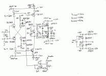
the picture I attach, contains one of my try to make nonfeedback amplifier. To reduce the distortion, I use large amount of local feedback. This sounds not so great, but I think that IRF mosfets caused the bad sound. If I have any time I will try it with CFP output stage....
sajti
Attachments
Sorry for the hungarian words. The IC makes the DC servo, and it connected to the output.
"ker" means ceramic capacitor.
sajti
"ker" means ceramic capacitor.
sajti
lumanauw said:
What's your suggestion on 2 TR servo like?
Just an idea/thought, not designed yet. But should be possible !
Mike
thanh said:mikeb! Can I view your schematic?🙂
Yes, i posted in lumanauws thread "transistor sounds".
Since the posting i added a buffer before vas and moved the cdoms
to the predriver.
PMA said:
Only in case that you succeed to inject any current into their gate .. 😉
Hmm, jfets have a leakagecurrent through the gate (<1na), not small
enough to be completely ignored...
to sajti:
These days i am experementing on a cfp-style mosfet out, i once
already had a similar circuit. This sounded very promising.
I finished prototype yesterday, but didn't work at all... 🙁
I never had very good results using irfs in a common way.
Mike
MikeB said:
Yes, i posted in lumanauws thread "transistor sounds".
Since the posting i added a buffer before vas and moved the cdoms
to the predriver.
Hmm, jfets have a leakagecurrent through the gate (<1na), not small
enough to be completely ignored...
to sajti:
These days i am experementing on a cfp-style mosfet out, i once
already had a similar circuit. This sounded very promising.
I finished prototype yesterday, but didn't work at all... 🙁
I never had very good results using irfs in a common way.
Mike
My amplier works without problem. So we can try to develop it together! If You put up Your amp, we can try to make better both of them!
sajti
sajti said:
My amplier works without problem. So we can try to develop it together! If You put up Your amp, we can try to make better both of them!
sajti
But this one is not nofeedback, its only lowfeedback (OLgain: ~1:8000)
I think i did some miswiring, i never had a circuit yet that works fine
in spice and not at all in real world. I will debug this evening.
If i get it run i will post the schematic. My topology is quite similar to yours,
but using jfets in the inputstage. (Some older design)
Its based on this:
http://www.diyaudio.com/forums/showthread.php?s=&threadid=32191&perpage=10&pagenumber=1
Mike
sajti said:
My amplier works without problem. So we can try to develop it together! If You put up Your amp, we can try to make better both of them!
sajti
Hi sajti !
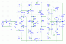
Here's a preview of my amp with this cfp-style mosfet out.
In the prototype i had to remove the c75, it caused oscillation.
Also instead of the zeners i used 2 red leds. It's not finished,
needs more testing and maybe more stabilizing.
The first test were good, but i haven't tested on my good speakers yet.
Mike
Attachments
MikeB said:
Hi sajti !
Here's a preview of my amp with this cfp-style mosfet out.
In the prototype i had to remove the c75, it caused oscillation.
Also instead of the zeners i used 2 red leds. It's not finished,
needs more testing and maybe more stabilizing.
The first test were good, but i haven't tested on my good speakers yet.
Mike
Looks good for me 🙂 C75 is the capacitor I recommended... But I never tried it with MOSFET. Thanks for the experience, it looks that this capacitor doesn't work with MOSFETs.
I recommend to try very small modification:
remove R79, and R80 from the ouput, and connect them directly to the drain of the output mosfets ( the lower pin of R79 to the upper pin of R68, and the symmetrical action for R69 and R80). This modificaton makes some feedback for DC too, and helps to regulate the bias when the amp heats up. Most of CFP I ever see use this connection.
sajti
I think the function of R79 and R80 is thermal stable . I have ever building a CFB output stage . With R79=R80=330 ohms , voltage which drop on R81 and R82 is stable.I recommend to try very small modification:
remove R79, and R80 from the ouput, and connect them directly to the drain of the output mosfets ( the lower pin of R79 to the upper pin of R68, and the symmetrical action for R69 and R80
If you connect a series diode with pin E of Q59 , you can have both stable and gain🙂
Have you ever tried to build a symmetrical current mirror?😀, i never had a circuit yet that works fine
in spice and not at all in real world
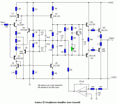
this is lotomo's design
Attachments
Hi !
Did some more tests... Was very dissapointing, weak bass, not really
clean sound and so on. Not really bad, but my other symetrical amp
is way better.
To thanh: yes, its some kind of symamp.
To sajti: I am familiar with normal CFP-output, in sims my config was
much better, more stable and less harmonics. The normal CFPout
showed massive 3rd harmonics. C75 is strange, i think it's only
amplyfing an existing stability problem. In sims this was absolutely
necessary, or crossconduction went up to 40ampere.
Thermal stability showed up ok in testings. I will try to stabilize the
circuit, if this doesn't improve the sound, this was my last amp using irfs.
What i don't understand: why does different topology always have
a that big impact on bass ? What does that mean ?
For example, i've built an asymamp, bass was good. I changed it to
symetrical, keeping the outputstage unmodified. And, wow the bass
kicked me from my couch...
And now, this topology has some badjoke-bass ?
Are my 4ohm-speakers too hard to drive ?
All 3 configs had comparable dampingfactors.
Mike
sajti said:
remove R79, and R80 from the ouput, and connect them directly to the drain of the output mosfets ( the lower pin of R79 to the upper pin of R68, and the symmetrical action for R69 and R80). This modificaton makes some feedback for DC too, and helps to regulate the bias when the amp heats up. Most of CFP I ever see use this connection.
sajti
Sorry, did not read correctly. I will try this modification. I thought
you meant connecting the emitters of the drivers directly to the
drain. This would be the standard cfp-output...
MikeB said:
Sorry, did not read correctly. I will try this modification. I thought
you meant connecting the emitters of the drivers directly to the
drain. This would be the standard cfp-output...
Yes. And if You keep the emitter resistors, and add two more resistors, You can get some voltage gain for the output stage, which can reduce the power loss, caused by the mosfet opening voltage.
sajti
sajti said:
Yes. And if You keep the emitter resistors, and add two more resistors, You can get some voltage gain for the output stage, which can reduce the power loss, caused by the mosfet opening voltage.
sajti
Yes, that's a nice way to get rid of this annoying high Vgs. I already
had simulated that, but not tried yet. Do you have experience with that ?
With that kind of output you get the voltageswing nearly to supplyvoltage,
only limited by RDSon.
Mike
MikeB said:
Yes, that's a nice way to get rid of this annoying high Vgs. I already
had simulated that, but not tried yet. Do you have experience with that ?
With that kind of output you get the voltageswing nearly to supplyvoltage,
only limited by RDSon.
Mike
I used it with BJT output stage. I guess that 1.2 - 1.3 is enough gain, to get the necessary 3-4V. With 33ohms emitter resistor, some 100-150ohms looks OK. For BJT stage I used gain 1.05-1.1 , because I need only 1-1.5V to avoid the losses.
In the weekend I will put up my nonfeedback amiplifier design. I want to buid it, in the next 2-3 weeks.
sajti
- Status
- Not open for further replies.
- Home
- Amplifiers
- Solid State
- Have you ever succeed in buiding a input stage with current mirror?


