Terry,
you just missed this one by Per Anders on the Leach clone a few days ago :
http://www.diyaudio.com/forums/showthread.php?s=&threadid=46824
There is lots of info on PCB-making on PCB software company homepages.
Designing a good PCB takes a lot of practice, making a PCB is rather easy.
Companies like Seno, that produce stuff to make PCB and layouts publish books on PCB making.
Some PCB design programs are freeware, with added features PCB software starts at $30/$40.
These are good for designing simple circuitry on 6"x4" boards.
Just some names that spring to my mind right now :
Orcad(Cadence)
Ultiboard(EWB)
PowerPCB(Pads)
ExpressPCB(same)
Eagle(Cadsoft)
Sprint Layout(Abacom)
Layo1(Baas)- probably just in Dutch
Cadstar(Zuken)
PCBdesigner(Pads)
It is also possible to draw PCB layouts in Autocad or similar, but even the simplest PCB software works much faster.
It takes a lot of hardware to produce professional quality PCB's.
I make my own for audio purposes because professionally produced Teflon PCB's are very expensive.
if someone else did the PCB design and you are able to join a group buy you are far better off i think.
jacco.
Thanks jacco,
I have contacted Jens Rasmussen about the group buy. Those are big boards! 😱
I'll have to do some more follow-up on it before I'm sure. I would like to find a project for this trannie and i like the idea of a big amp. 😀
Blessings, Terry
I have contacted Jens Rasmussen about the group buy. Those are big boards! 😱
I'll have to do some more follow-up on it before I'm sure. I would like to find a project for this trannie and i like the idea of a big amp. 😀
Blessings, Terry
Before you go crazy, I would finish the Rod Elliot amp you are presently working on. This hobby can be expensive if you start many projects and finish none.
kilowattski said:Before you go crazy, I would finish the Rod Elliot amp you are presently working on. This hobby can be expensive if you start many projects and finish none.
I know how that can go. I have only a couple of parts yet to get. They should arrive Monday. I also need to get some more aluminum for the chassis. I thought I had what I needed but couldn't find it. Today being New Year's day, none of the metal suppliers were open.

Probably have to wait until Monday for those too. I should have it together by mid week. Really looking forward to hearing it. I will probably build a stereo P101 when it is done for the rear two channels. Depends on how much better it sounds than my Soundcraftsmen amps. Otherwise I'll just use one of the Soundcraftsmen amps for that.
I've also thought about using the bigger tranny to make a variable power supply by using it with my variac. We'll see. If I can find a good amp design to use it I'll probably still build it.
Blessings, Terry
hey ...
I'm a PCB designer and more than willing to help ... I was lurking here to find some ideas and more I look at it .. I think a generic chassis design would be of the greatest benefit to diyaudio ...
let me know
thanx
TVP
I'm a PCB designer and more than willing to help ... I was lurking here to find some ideas and more I look at it .. I think a generic chassis design would be of the greatest benefit to diyaudio ...
let me know
thanx
TVP
TVP,
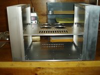
I could not agree more. It seems that the electronics portion of a project is cake compared to the mechanical portion. I built a Zen IV amp and building the boards and wiring took all of about 8 hours but the chassis took about 3 months of Saturdays at a neighbors machine shop. Granted, some of the time was spent learning how to use a Bridgeport, but it still seemed to take forever. Below is a picture of the chassis. It sure would be nice to have a chassis I could purchase easily. Most of the chassis you can purchase are in Europe or the Far East.
I could not agree more. It seems that the electronics portion of a project is cake compared to the mechanical portion. I built a Zen IV amp and building the boards and wiring took all of about 8 hours but the chassis took about 3 months of Saturdays at a neighbors machine shop. Granted, some of the time was spent learning how to use a Bridgeport, but it still seemed to take forever. Below is a picture of the chassis. It sure would be nice to have a chassis I could purchase easily. Most of the chassis you can purchase are in Europe or the Far East.
Attachments
I doubt that you will ever buy a complete chassis of the same quality you built.
But you are right that it is a waste of energy if every DIY artist needs to go though the learning process of machining.
I grew up between machinery, a chassis like cowanrq built i would never do myself because of the time involved.
If offered at a reasonable pricetag and within reach i would certainly buy such chassis.
Ready built original Aleph style chassis like the one offered from Asia look non-DIY and can be made affordable, those i can imagine to be attractive for a great number of amp builders, in the US and the fossil continent.
hey all ....
sorry about the tangent topic , I can't start my own yet 🙁
I've been thinking about the chassis idea long before I started a amp design ... I've been doing this so long, I guess it's always how I've done it . I can ALWAYS make a PCB fit a chassis, going the other way around never seems to work :\ anyway ....
If you guys are interested ... PLEASE ... start a topic and lets get this going !!! I'd start my own if I could 🙁 ... I'm going to do a rack ANYWAY .... so I'd like to get as many ideas into it QUICKLY !!!!
My idea is to have a chassis with a power supply area (below) and then cards that slide in (top)... heatsink on top of the card cage ... more of a power and heat management system ... but then it can be built as 200watts or 5000watts (multichannel of course) and you can change card/amps to play with ... side by side with ONE power supply system 🙂 Common card layouts for audio in and out .. common power from the back of the cage ...
perf PCBs could be made for true experiments .... common amp designs for testing output devices ???? maybe make the power supply a card too ???? then one could be made for car stereo 🙂
lots of ideas in my head .... few on paper .... CAD work to start soon 🙂
let me know
thanx
TVP
TVP,
Welcome to the forum. Don't forget to check the "I've searched" box in the upper left hand corner of the new thread form. That's bittten me more than once. I don't remember if being under moderation prevents you from starting a thread or not.
Bob
Welcome to the forum. Don't forget to check the "I've searched" box in the upper left hand corner of the new thread form. That's bittten me more than once. I don't remember if being under moderation prevents you from starting a thread or not.
Bob
That's bittten me more than once.
perspectives...I've often contributed bits which ended up in different threads...no intention, sometimes can't be helped when my line up here runs at 30Kbps!
rich
Hey guys, I'm almost ready to start putting this thing together. I've been bouncing back and forth between building the Low TIM and the Superamp. The Low TIM would require beefier transistors and more of them and even then, that design has not been tested. Frome what I can tell, several folks have built the Superamp, so that is probably my best option.
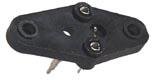
I have a question about the TO-3 transistors. Is it OK to use sockets like this or this?
Would I be better off with mica insulators?
I have both styles of transisors for this amp (TO-3 TO-247). I should have the Press-n-Peel sheets and copper clad boards by the end of the week and like to ready to start putting this together.
Thanks, Terry
Attachments
For audio purposes sockets are not the best choice.
Besides the thermal issue, with a high power amplifier cooling is an important factor, there is an audio signal going through the contacts.
Microphonics may change contact resistance of the sockets, and influence sound quality.
In time, contact resistance will deteriorate by corrosion and/or
smudge (look at the insides of a ten year old amplifier).
For proper amplifiers sockets are not used at any location, not for small signal devices or operational amplifiers.
If used, commonly the devices legs are soldered in the socket.
The easiest would be mica isolators, Mr Pass told me they are still the number 1 choice.
For TO3's you might consider AluminumOxide isolators, the same shape as the mica isolators, a white color and about 1/8 " thick.
I used them for a hybrid class A amplifier for Hitachi 50/135 Mosfet outputs.
Thermal resistance of AlOx isolators is a lot better than Mica, but a bit more expensive.
Though not strictly necessary some amplifier builders use them, a personal thing i guess.
Thermal grease you will need just the same.
My personal recommendation would be to use solder with a silver percentage.
Soldering with the stuff is great, it looks better and keeps the appearance.
In my view using silver solder minimises the risk of making a bad connection and sound quality is better.
After soldering i clean boards to take the solder resin remains off and put a cover of plastic spray on it.
Sockets (for TO3s) help isolate the case from the heatsink where screws pass through. I understand and agree that soldered connections are better. I am actually planning on using sockets, but soldering the pins to the socket after the amp is tested and working.
-b
-b
Hi,
AlO at .125inch is far too thick for effective thermal conduction.
It should be 50 to 100 times thinner.
Sockets in general will reduce the thermal performance of hi power devices. Avoid them if possible.
regards Andrew T.
AlO at .125inch is far too thick for effective thermal conduction.
It should be 50 to 100 times thinner.
Sockets in general will reduce the thermal performance of hi power devices. Avoid them if possible.
regards Andrew T.
Thanks guys,
I was afraid that the socket might reduce the heat transfer to the heatsink. I had better just stick to the mica pads and grease.
Thanks again,
Terry
I was afraid that the socket might reduce the heat transfer to the heatsink. I had better just stick to the mica pads and grease.
Thanks again,
Terry
Could someone remind me of how the socket affects the heat transfer to the heatsink? The socket mounts on the opposite side of the heatsink from the device, so the device sits on isolator (pad or mica) the same with or without the socket.
What am I missing?
-b
What am I missing?
-b
I didn't realize that they were on the opposite side of the heatsink. That makes more sense. I guess the mica pads and grease are still necessary then.
On the Leach there are connections to the case as well. I suppose I would need some solder tabs for the bolts as well.
Thanks, Terry
On the Leach there are connections to the case as well. I suppose I would need some solder tabs for the bolts as well.
Thanks, Terry
WorkingAtHome said:The socket mounts on the opposite side of the heatsink from the device
As far as i got the information right torque distribution of the TO3 is more likely to be uneven if sockets are used, resulting in a higher thermal resistance between the TO3 and the heatsink.
The socket goes between the heatsink and the screw that pulls the bolt, and the TO3, to the heatsink.
A regular bolt and screw with an isolator pulls the device more evenly to the heatsink.
As regular habit became to integrate the TO3 connections on pcb's sockets were used more sparsely.
The major downside of sockets would be the unsoldered connection, and in case of the wires plugged in the socket double contacts in the signal way.
I noticed that on the Pass labs F1 large washers are mounted on the output devices, aimed at getting an even better torque distribution.
AndrewT said:It should be 50 to 100 times thinner.
Hi Andrew,
do thin Aluminum Oxide isolators exist?
I have never seen them thinner than the ones i have, i am told they need to be that thick for strength.
At the time i bought them they were 10 times more expensive then Mica, 10 times more difficult to obtain.
If unevenly torqued they tear, so mounting them takes much more care then with mica.
For TO3's mica was listed at 0.30 , Al-Oxide came a bit over 0.20
Cheers,
jacco.
- Status
- Not open for further replies.
- Home
- Amplifiers
- Solid State
- Have transformer, will build