Thanks for the apology........ Appreciated 👍It still boggles my brain that the RIAA EQ that is applied to a record is called "inverse" RIAA EQ instead of RIAA EQ.
To the quote.........
Your lack of technical skills/insight (NO pun intended) makes it quite understandable, that you "boggle" with this.
What is done to LP´s when recording them, and what a phono (riaa) preamp does to the signal, are indeed both
"riaa curves", but one does the opposite of the other.
Since the schematic you´ve been given by Marcel most often is used to test, how close (accurate) the riaa curve is followed
in a phono preamp, is called "Inverse Riaa Circuit", most people find it natural to call it "Inverse Riaa", and since it does the same
to the signal, as what is done to the signal when recording a LP, it certainly makes most sense to call the process "Inverse Riaa".
Recorcing Industry Association of America (riaa) made a curve to get room for longer playback.
Some could argue then, that what the phono-preamp does to the signal is in fact the "reverse/inverse" riaa curve.
Both would be right 😉
When you demanded, that we called it a term, that YOU understood, I for one dropped out of the discussion. That only helps
you, and confuses a lot of others. @MarcelvdG didn´t though....... Kudos to him 👍
Whish you the best of luck with your progress !!
Last edited:

I am sure that I can tap into the DAC's analog output without cutting any traces. Others have done that when they do the Lampization mod. I will remove the op amp chips and put an empty 8 pin DIP socket in its place. I just need to figure out where the best place to solder a short piece of coax to send the current to the EQ board will be.Others have been so nice to warn you that this is technically not a very good solution. I agree with that, but I have seen people on this and other audio forums do stranger things and be happy with the result, so why not try it?
You will have to disconnect the DAC outputs from the op-amp current-to-voltage converters inside the CD player. Can you do that without causing unrepairable damage? Otherwise you can't revert the change if you don't like the results.
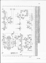
Here is the schematic that shows the DAC and op amp circuits.
Attachments
I have ordered a couple each of solderless bread boards and prototyping PCBs. I think I will start with a solderless breadboard to test if the circuit works. If it does at at least sounds OK even if not great, I will buy better quality components and try get the values as exact as possible by making each resistor and capacitor value more accurate by using components in parallel / series (as needed) to equal the exact target values.
See an example on Pg. 3 & 4 of the linked PDF. (You might have to C&P to open the link).
https://hifisonix.com/wp-content/uploads/2016/12/Accurate-Inverse-RIAA.pdf
See an example on Pg. 3 & 4 of the linked PDF. (You might have to C&P to open the link).
https://hifisonix.com/wp-content/uploads/2016/12/Accurate-Inverse-RIAA.pdf
Last edited:
I am confused. Are you saying that 52.65 ohms is the ideal value that I would install for R4 or that it is a value that would be used to calculate the actual resistor taking the 47K ohms of the preamp input impedance into account? I hope my question makes some kind of sense. If it does, can you please tell me what value resistor I should install for R4?By the way, when you change R4 to 52.65 Ω including the parallel resistance across the MC amplifier input, C1 and C2 get within 1.4 % from an E6 standard capacitor value:
R1 = 10 Ω
R4 = 52.65 Ω including the MC amplifier input resistance that is in parallel
For example, the resistor on the board has to be 69.21422 Ω, or 69.8 Ω rounded to the nearest E96 value, when the MC amplifier input resistance is 220 Ω. It has to be 111.19324 Ω, or 110 Ω rounded to the nearest E96 value, when the MC amplifier input resistance is 100 Ω.
R3 = 759.646247223 Ω -> 750 Ω rounded to an E96 value
C2 = 98.730165882 nF -> 100 nF rounded to an E6 value
R2 = 9510.7946895155 Ω -> 9530 Ω rounded to an E96 value
C1 = 334.35691799 nF -> 330 nF rounded to an E6 value
The capacitors either have to be accurate film capacitors or accurate NP0 a.k.a. C0G ceramic multilayer capacitors, definitely not ceramic class 2 or 3 capacitors (such as X7R, X5R, Y5V, Z5U). The more accurate the better, but the best you can get with these values is probably +/- 5 % tolerance.
There are infinitely many possibilities, but naming two:
1. Standard values, no series or parallel connections
I usually like to avoid series and parallel connections when possible. For that case, my latest and greatest values would be:
R1 = 10 Ω
R4 = 52.3 Ω on the board in parallel with the 47 kΩ of the amplifier
R3 = 750 Ω
C2 = 100 nF
R2 = 9530 Ω
C1 = 330 nF
All these resistor values are E96 standard values, all capacitor values are E6 standard values. I have rounded things off to these standard values, but the round-off errors are all below 1.4 %.
2. Series and parallel connections
If you prefer to connect things in parallel or series, the values from post #72 are probably more convenient, because the capacitances there are both somewhat above standard values. The 47 kΩ from the preamplifier is then one of the resistors used to realize R4, so you need to put 49.95303524 Ω on the board to get to the required 49.9 Ω.
In either case, the capacitors either have to be accurate film capacitors or accurate NP0 a.k.a. C0G ceramic multilayer capacitors, definitely not ceramic class 2 or 3 capacitors (such as X7R, X5R, Y5V, Z5U). The more accurate the better, but the best you can get with these values is probably +/- 5 % tolerance.
Last edited:
Would 2W resistors and 25V caps be sufficient ratings? I have found NPO ceramic 25V caps with 1% tolerance and am looking for 1% tolerance precision metal film resistors.By the way, when you change R4 to 52.65 Ω including the parallel resistance across the MC amplifier input, C1 and C2 get within 1.4 % from an E6 standard capacitor value:
R1 = 10 Ω
R4 = 52.65 Ω including the MC amplifier input resistance that is in parallel
For example, the resistor on the board has to be 69.21422 Ω, or 69.8 Ω rounded to the nearest E96 value, when the MC amplifier input resistance is 220 Ω. It has to be 111.19324 Ω, or 110 Ω rounded to the nearest E96 value, when the MC amplifier input resistance is 100 Ω.
R3 = 759.646247223 Ω -> 750 Ω rounded to an E96 value
C2 = 98.730165882 nF -> 100 nF rounded to an E6 value
R2 = 9510.7946895155 Ω -> 9530 Ω rounded to an E96 value
C1 = 334.35691799 nF -> 330 nF rounded to an E6 value
The capacitors either have to be accurate film capacitors or accurate NP0 a.k.a. C0G ceramic multilayer capacitors, definitely not ceramic class 2 or 3 capacitors (such as X7R, X5R, Y5V, Z5U). The more accurate the better, but the best you can get with these values is probably +/- 5 % tolerance.
I was building a BOM to order parts and looked at order that I placed when I was going to build a Lampizator output.There are infinitely many possibilities, but naming two:
1. Standard values, no series or parallel connections
I usually like to avoid series and parallel connections when possible. For that case, my latest and greatest values would be:
R1 = 10 Ω
R4 = 52.3 Ω on the board in parallel with the 47 kΩ of the amplifier
R3 = 750 Ω
C2 = 100 nF
R2 = 9530 Ω
C1 = 330 nF
All these resistor values are E96 standard values, all capacitor values are E6 standard values. I have rounded things off to these standard values, but the round-off errors are all below 1.4 %.
2. Series and parallel connections
If you prefer to connect things in parallel or series, the values from post #72 are probably more convenient, because the capacitances there are both somewhat above standard values. The 47 kΩ from the preamplifier is then one of the resistors used to realize R4, so you need to put 49.95303524 Ω on the board to get to the required 49.9 Ω.
In either case, the capacitors either have to be accurate film capacitors or accurate NP0 a.k.a. C0G ceramic multilayer capacitors, definitely not ceramic class 2 or 3 capacitors (such as X7R, X5R, Y5V, Z5U). The more accurate the better, but the best you can get with these values is probably +/- 5 % tolerance.
The Z foil resistor that I ordered for I/V conversion when I was planning to build a Lampizator output is actually 100 ohms not 10 ohms as I thought from memory. Does this mean that the values of the components for IRIAA will need to be change or that the output voltage of the IRAA circuit will be so high that it will overload my phono stage .
The first question is how much the DAC performance degrades with a 100 ohm load, and I don't know the answer to that. I only know you will violate the TDA1541A output voltage compliance specification by about a factor of 16 with such a high resistor value; the voltage compliance spec is likely to be a bit conservative, but a factor of 16 is a lot.
I would just buy a couple of 10 ohm run-of-the-mill metal film resistors and leave the Z foil resistors unused.
Yes, more than enough. 0.6 W would also be more than enough.
I would just buy a couple of 10 ohm run-of-the-mill metal film resistors and leave the Z foil resistors unused.
Would 2W resistors and 25V caps be sufficient ratings?
Yes, more than enough. 0.6 W would also be more than enough.
According to my THD measurement using various I/V resistors, up to 33R there is no increase of THD. If 2 mA bias current is injected in the output of the DAC, you can double the value of this resistor.
https://www.diyaudio.com/community/...ac-using-tda1541a.79452/page-452#post-7763363
https://www.diyaudio.com/community/...ac-using-tda1541a.79452/page-452#post-7763412
https://www.diyaudio.com/community/...ac-using-tda1541a.79452/page-452#post-7763363
https://www.diyaudio.com/community/...ac-using-tda1541a.79452/page-452#post-7763412
Last edited:
After looking at what you have posted I am leaning towards using a 33 ohm resistor for I/V conversion.According to my THD measurement using various I/V resistors, up to 33R there is no increase of THD. If 2 mA bias current is injected in the output of the DAC, you can double the value of this resistor.
https://www.diyaudio.com/community/...ac-using-tda1541a.79452/page-452#post-7763363
https://www.diyaudio.com/community/...ac-using-tda1541a.79452/page-452#post-7763412
Here is the detailed data for the analog out current of the TDA1541:
The TDA1541 has a typical full-scale current output of 4mA peak-to-peak (4mA p-p). This translates to 1.41mA RMS. At digital zero, the output current is 2mA. The TDA1541 uses a unipolar output current.
Based on this data it seems that in the best case scenario even with a 33 ohm resistor for I/V, the output of the IRIAA circuit will overload my preamp output stage capabilities. Using ohms law to calculate the I/V converted voltage, I get about 66mv. The highest output phono cartridges have an output of about 6mv.
How will I be able to get the voltage down to a usable voltage of say 2-3mv?
Please look at my response to Icsaszar in post #113 regarding the voltage creating an overlaid of the phono stage of my preamp.OK, so 10 ohm is perfectly OK and 100 ohm is not.
Repeating a part of post #95:
The resistor R1 of the circuit is supposed to be the current-to-voltage converting resistor. I've chosen 10 Ω because I thought I read in one of the posts of this thread that the DAC works well with 10 Ω. With a 4 mA peak-peak output current, the voltage across the 10 Ω would be 40 mV peak-peak or about 14 mV RMS.
At 1 kHz, the output voltage of the circuit is about twenty times less than the voltage across R1, so around 0.7 mV RMS. That's about 7 dB to 8 dB more than the 0.3 mV from your MC cartridge, but this is a maximum level, while cartridge levels are usually nominal levels. Chances are that the DAC will sound slightly softer than the cartridge.
Thanks. I was very tired when I wrote that post last night. Today, I don't know how I came up with 66mv. 🙂
No problem.
Just being curious: what time zone are you in? According to your profile you are from Portland, so it should be 9 hours earlier at your location than here (it's central European summer time here), but then it must have been afternoon for you rather than night.
Just being curious: what time zone are you in? According to your profile you are from Portland, so it should be 9 hours earlier at your location than here (it's central European summer time here), but then it must have been afternoon for you rather than night.
Wait a minute. When I read the comments about RIAA I got it backward in my brain. The LPs have RIAA pre-emphasis equalization applied in the mastering process and my preamp has an inverse RIAA equalization filter in it. Sooooo... I would need to apply RIAA equalization to the output of the I/V converted signal from my DAC
Inverse RIAA is applied in the recording process. This is what you need to mimic,
In below link, you need to create the blue dotted curve, which is the inverse RIAA.
https://en.wikipedia.org/wiki/RIAA_equalization
https://hagerman-audio-labs.myshopify.com/products/iriaa2-inverse-riaa-filter
Also some good documents in the second link.
Btw - Op-amps are not a bad thing 🙂
Last edited:
Just a little addition: the direction of the current is towards the output, i.e. sink. Better to say it is 0 ... -4 mA. Using an inverting op.amp. we get noninverted voltage. On an I/V resistor we get inverted voltage. If this inverted/noninverted thing matters at all, I mean audibly.Here is the detailed data for the analog out current of the TDA1541:
The TDA1541 has a typical full-scale current output of 4mA peak-to-peak (4mA p-p). This translates to 1.41mA RMS. At digital zero, the output current is 2mA. The TDA1541 uses a unipolar output current.
That is interesting. I looked at the times shown for my posts and many seem to be incorrect. I wonder if it is because I block the location of my laptop. I am in fact in Portland, OR. I looked in my profile and account for a time zone setting but could not find one.No problem.
Just being curious: what time zone are you in? According to your profile you are from Portland, so it should be 9 hours earlier at your location than here (it's central European summer time here), but then it must have been afternoon for you rather than night.
I want to thank you again for all of your help. I too am curious because you seem very knowledgeable. Are you an professional electronics engineer or just an amateur with many years of experience?
Please look at Icsaszar's post 119. I have never paid much attention to whether the equipment in my system is inverting or non-inverting output but I think they are all non-inverting at any stage. How might this IRIAA circuit affect the sound of my system?
PS: It is 1:42 PM here as I post this so maybe when I "think" I made posts is only in my brain due to my medications often making me feel sleepy.. LOL
- Home
- Source & Line
- Digital Source
- Has Anyone Tried to Use a TDA1541 DAC to Feed a Phono Preamp?