Hi Edmond
Sorry I didnt get the paper accross yet, the mail came back, file to large. Im trying to get a link for whre it is then Ill mail it to you.
Sorry I didnt get the paper accross yet, the mail came back, file to large. Im trying to get a link for whre it is then Ill mail it to you.
Hi David,
Now I completely understand what you mean, see below. After some modifications I got this circuit more or less stable...
Cheers,
E.
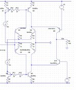
While I think about this - I have a question about the more practical implementation of it shown in Fig. 9 on your website.
Do we really need Q23 and Q24? What happens if you delete them and limit the fault current with resistors in the collectors of Q21 and Q22?
And thank you for the email, more to think about
David
Last edited:
protection
Hi David,
Q23 and Q24 protect the VAS trannies against excessive collector currents during overload conditions, at least that is the intention. However, a quick sim learned that it didn't work in this particular case, because the VAS output isn't loaded at all (the circuit isn't complete).
A typical OPS short circuit protection, for example, shortens the VAS-output to the OPS-output and in that case Q23 or Q24 would limit the VAS current.
Cheers,
E.
OND-FB
Hi Alex,
After reading the article, I think that OND-FB is nothing else than a double error feedback system. Presumable they call it OND-FB, because second FB loop (tries to) remove the last traces of distortion. Nevertheless, I consider OND-FB a misnomer, as the FB loops act on the whole signal, and not only on distortion or noise (FB=FB=FB period). IOW, it's indeed nothing but marketing bla bla.
I also saw that no global NFB was applied. This explains why the distortion of the Luxman B-1000F amp is rather high.
Anyway, thanks for the article.
Cheers,
E.
PS: I've updated the website with a new version of the amp of fig.12 plus graphs of all six FB loops.
I just started looking at it last night, send me your email via pm, Ill show you a complete study of this OND.
Well as you know by now, their is always marketing mambo jumbo added to sell amps that cost thousands, I guess it helps to raise sales.
Hi Alex,
After reading the article, I think that OND-FB is nothing else than a double error feedback system. Presumable they call it OND-FB, because second FB loop (tries to) remove the last traces of distortion. Nevertheless, I consider OND-FB a misnomer, as the FB loops act on the whole signal, and not only on distortion or noise (FB=FB=FB period). IOW, it's indeed nothing but marketing bla bla.
I also saw that no global NFB was applied. This explains why the distortion of the Luxman B-1000F amp is rather high.
Anyway, thanks for the article.
Cheers,
E.
PS: I've updated the website with a new version of the amp of fig.12 plus graphs of all six FB loops.
ODNF
Hi Edmond,
You know this link?
Only Distortion Negative Feedback Circuit
It shows some examples of OND or ODNF.
Cheers, Steven
Hi Edmond,
You know this link?
Only Distortion Negative Feedback Circuit
It shows some examples of OND or ODNF.
Cheers, Steven
Hi Edmond,
You know this link?
Only Distortion Negative Feedback Circuit
It shows some examples of OND or ODNF.
Cheers, Steven
without separate power amp paths and a power level signal combiner (Black's Feedforward, Quad Current Dumping), any such feedback amp topology turns out to be equivalent to any other - with the possible addition of pre-filter to turn 1-degree of freedom system into the more general 2-degree of freedom system where feedback/desensitivity doesn't constrain frequency/step response
it seems to be really hard to get many people up to speed on 49 yr old textbook feedback theory fundamentals:
http://www.diyaudio.com/forums/soli...terview-error-correction-112.html#post1070802
Last edited:

There's still a lot of work to be done: Finding an optimal compensation scheme (better phase margin) and improving the step response of the amp of fig.12. Simulations aren't that simple and easy.
Cheers,
E.

Miller compensation, be it two pole or TMC, is not possible because the second stage does not phase invert. One, alas, is left with shunt compensation to ground from the output of the second stage.
Hi David,
Q23 and Q24 protect the VAS trannies against excessive collector currents during overload conditions, at least that is the intention. However, a quick sim learned that it didn't work in this particular case, because the VAS output isn't loaded at all (the circuit isn't complete).
A typical OPS short circuit protection, for example, shortens the VAS-output to the OPS-output and in that case Q23 or Q24 would limit the VAS current.
Cheers,
E.
Yes, I understand their purpose. Bob Cordell discusses them a bit too. What I asked was whether it would be effective to protect the VAS trannies in a simpler way. That is, with resistors in collectors of the beta enhancement transistors to limit their current into the VAS trannies. I have seen this used but not really analysed. What are the trade-offs of a resistance in the collector of the emitter follower?
Best wishes
David
it seems to be really hard to get many people up to speed on 49 yr old textbook feedback theory fundamentals:
A while back I was inspired by Ed Cherry's references to read Bode's book.
Words fail me, that book is the source!! In 1945! So much deeper than modern rehashes.
Only one problem. He says he became 'invincibly' tired and didn't write the final planned chapter on multi-loop feedback. I am a bit reassured that if even Bode found it hard work then no wonder I do. But I really miss that chapter.
I followed one of your earlier references and read B.J. Lurie. "Feedback maximization" but it's not that clearly written. Perhaps it helps to read Russian.
The Horowitz book looks pretty helpful.
Do you have any other recommendations to read?
Best wishes
David
Last edited:
Hi Arthur,
Here they are:
Cheers,
E.
The 1381 and 3503 models don't seem to have a TF😱
Isn't that kind of important?😉
Best Wishes
David
without separate power amp paths and a power level signal combiner (Black's Feedforward, Quad Current Dumping), any such feedback amp topology turns out to be equivalent to any other - with the possible addition of pre-filter to turn 1-degree of freedom system into the more general 2-degree of freedom system where feedback/desensitivity doesn't constrain frequency/step response
it seems to be really hard to get many people up to speed on 49 yr old textbook feedback theory fundamentals:
http://www.diyaudio.com/forums/soli...terview-error-correction-112.html#post1070802
But if the error correction is applied to a stage with gain, creating a positive feedback loop then the transfer function can get much different to 'normal' feedback theory.
TF parameters
Hi David.
You're a very astute observer. Indeed, the (optional) TF parameters are missing. Don't ask me how or why this happened. 😕
They seem to be not that important, because simulation results from the Andy-Bob models were almost identical. Despite of that, I will use these models from now on.
BTW, the TR parameters are also missing.
Cheers,
E.
The 1381 and 3503 models don't seem to have a TF😱
Isn't that kind of important?😉
Best Wishes
David
Hi David.
You're a very astute observer. Indeed, the (optional) TF parameters are missing. Don't ask me how or why this happened. 😕
They seem to be not that important, because simulation results from the Andy-Bob models were almost identical. Despite of that, I will use these models from now on.
BTW, the TR parameters are also missing.
Cheers,
E.
Hi Edmond,
I don't see the TF parameter in the SPICE model as being particularly optional. It sets the ft (speed) of the transistor (at low current Cje also comes to dominate ft). I forget if SPICE has a default value for TF, but it is probably zero, making for extremely high ft at medium to high collector currents. This might yield unrealistically optimistic results for stability.
Cheers,
Bob
I don't see the TF parameter in the SPICE model as being particularly optional. It sets the ft (speed) of the transistor (at low current Cje also comes to dominate ft). I forget if SPICE has a default value for TF, but it is probably zero, making for extremely high ft at medium to high collector currents. This might yield unrealistically optimistic results for stability.
...while Edmond is still hoping somebody will invest time and money to build this stuff
 . I have looked into the autobias output stage, using the best models in our university lab, and it is at best marginally stable.
- Status
- Not open for further replies.
- Home
- Amplifiers
- Solid State
- Has anyone seen this front-end before?