Edmond have you perhaps experimented with OND feedback. ( Distortion only feedback)
Scheme that luxman has been using in its latest amps, seems to have benefits and better results compared to EC.
Perhaps this is topic is better suited in your other thread.
Scheme that luxman has been using in its latest amps, seems to have benefits and better results compared to EC.
Perhaps this is topic is better suited in your other thread.
ONDFB
Hi Alex,
Never heard of OND feedback.
Luxman claims that it is a feedback system that only removes elements of noise and distortion while not affecting the music. How on earth they do that? By separating noisy electrons from musical electrons? 🙄
Do you have (a link to ) a schematic?
According to Stereophile, the Luxman B-1000F distorts 300ppm at 20kHz and 20V into 4 Ohms. Sorry, but I'm not impressed at all. 🙁
>Perhaps this topic is better suited in your other thread.
Sure, another thread. Let's call it 'The most expensive distortion generators on the market'. 😀
Cheers,
E.
I just started looking at it last night, send me your email via pm, Ill show you a complete study of this OND.
Well as you know by now, their is always marketing mambo jumbo added to sell amps that cost thousands, I guess it helps to raise sales.
Well as you know by now, their is always marketing mambo jumbo added to sell amps that cost thousands, I guess it helps to raise sales.
Last edited:
My Clipping simulations
Hello Edmond,
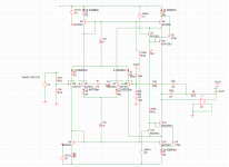
Attached is the circuit I used for the 20Khz simulation (its your barebones figure 5 circuit).
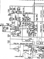
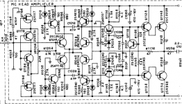
Funny that Luxman should be mentioned, The Luxman M-05 and C-05 preamp used circuits less refined but along the lines of whats being discussed here. See attachments first M-05 poweramp then C-05 preamp
Regards
Arthur
Hello Edmond,
Attached is the circuit I used for the 20Khz simulation (its your barebones figure 5 circuit).
Funny that Luxman should be mentioned, The Luxman M-05 and C-05 preamp used circuits less refined but along the lines of whats being discussed here. See attachments first M-05 poweramp then C-05 preamp
Regards
Arthur
Attachments
Hello Edmond,
The Luxman manuals are easy to get off the web , but I can send them to you if you want them.
Regards
Arthur
The Luxman manuals are easy to get off the web , but I can send them to you if you want them.
Regards
Arthur
Hello Alex
Which amp are you talking about the Luxman B-1000F or another model , I am also interested.
Regards
Arthur
Which amp are you talking about the Luxman B-1000F or another model , I am also interested.
Regards
Arthur
Hello Edmond,
Attached is the circuit I used for the 20Khz simulation (its your barebones figure 5 circuit).
Funny that Luxman should be mentioned, The Luxman M-05 and C-05 preamp used circuits less refined but along the lines of whats being discussed here. See attachments first M-05 poweramp then C-05 preamp
Regards
Arthur
Since the circuit is fully symmetrical the lack of symmetry in the waveform suggests a model problem. What models and simulator did you use?
This assumes that your schematic is correct.
Hello Pete,
The following are the models I use.
Regards
Arthur
The following are the models I use.
Regards
Arthur
Attachments
Last edited:
Are the KSA and KSC models the ones from andy_c's old forum?
There were several revisions if I remember correctly, and it is
unfortunate that he took the site offline.
What simulator are you using just out of curiousity?
There were several revisions if I remember correctly, and it is
unfortunate that he took the site offline.
What simulator are you using just out of curiousity?
Last edited:
At the least the KSA1381 model looks suspect. Some parameters are stated to 5 place accuracy while others are just round number defaults and some aren't within cooee of reasonable. For instance the VAF is way too low and RB is about 100 times too small. It doesn't inspire confidence. Bob Cordell has better models for this and the 3503 too.
Best wishes
David
Best wishes
David
Last edited:
Hello Pete,
The following are the models I use.
Regards
Arthur
Hi Arthur,
Try using the KSA1381C and KSC3503C models from my site at CordellAudio.com - Home.
Cheers,
Bob
Are the KSA and KSC models the ones from andy_c's old forum?
Also tested by myself against the datasheet, much better in the Ft-Ic department compared to the original Fairchild models or any other that I have seen so far.
** Creation: Mar.-11-2008 Rev: 0.0
** Fairchild Semiconductor
**
** Modified by Andy - Rev. 3, Dec. 7, 2010
**
** Original, unchanged Fairchild parameters
**-------------------------------------------------------------------
.MODEL Q2SC3503 NPN(
+ IS=7.010E-13
+ BF=156.09
+ IKF=0.12325
+ ISE=1.2538E-14
+ NE=1.5
+ BR=0.64499
+ VAR=100
+ IKR=0.05102
+ ISC=6.4644E-09
+ NC=1.5
+ RE=0.108
+ RC=1.215
+ RB=12.134
+ RBM=0.034
+ IRB=3.0e-6
+ VTF=35
+ TR=1.0E-8
+ EG=0.76
+ XTB=1.5
**-------------------------------------------------------------------
** Parameters modified by Andy
**
** Early Voltage from Glen's curve tracer measurements
+ VAF=1000
**
** fT-related parameters from Matlab optimization
+ CJC=11.35E-12
+ MJC=0.3160
+ VJC=0.2
+ FC=0.950383
+ TF=1.6933e-010
+ XTF=10000
+ CJE=5.621e-011
+ VJE=0.645139
+ MJE=0.6
+ ITF=7.50579)
*$
************ Power Discrete BJT Electrical Circuit Model ***************
** Product: KSA1381
** Package: TO-126
** CRT Display, Video Output
**
** Modified by Andy - Rev. 3, Dec. 7, 2010
**
** Original, unchanged Fairchild parameters
**----------------------------------------------------------------------
.MODEL Q2SA1381 pnp(
+ IS = 5.5544E-14
+ BF = 148
+ BR = 1.592
+ ISE = 2.0546E-15
+ NE = 1.5
+ ISC = 3.24807E-10
+ NC = 2
+ VAF = 580
+ VAR = 100
+ IKF = 0.2163
+ IKR = 0.087544
+ RB = 10.18
+ RE = 0.0512
+ RC = 4.072
+ XTB = 0.907
+ EG = 0.62
+ XTI = 3
+ NK = 0.5
+ NF = 1
**----------------------------------------------------------------------
** Parameters modified by Andy
** fT-related parameters from Matlab optimization
+ CJC=13.4777e-12
+ MJC=0.2951
+ VJC=0.2000
+ FC=0.924467
+ TF=5.5166e-010
+ XTF=10000
+ CJE=3.785e-011
+ VJE=0.653329
+ MJE=0.473845
+ ITF=11.3302
+ VTF=35)
*$
clipping
Hi Arhur,
I seemed that the RCO = 50.1187 parameter in your KSC3503 model is the culprit. This parameter, together with QCO, VO and GAMMA has something to do with modeling of quasisaturation, see: bjt spice parameters - Google zoeken
If you comment out RCO (and the other three parameters), clipping looks fine.
Also VAF=100 in the KSA1381 model is too low. The real Early voltage of a KSA1381-E is about 400V (@ Ic = 5 ... 15mA)
edit: and the real Early voltage of a KSC3503-D is about 700V.
Cheers,
E.
Hello Edmond,
Attached is the circuit I used for the 20Khz simulation (its your barebones figure 5 circuit).
[..]
Regards
Arthur
Hello Pete,
The following are the models I use.
Regards
Arthur
Hi Arhur,
I seemed that the RCO = 50.1187 parameter in your KSC3503 model is the culprit. This parameter, together with QCO, VO and GAMMA has something to do with modeling of quasisaturation, see: bjt spice parameters - Google zoeken
If you comment out RCO (and the other three parameters), clipping looks fine.
Also VAF=100 in the KSA1381 model is too low. The real Early voltage of a KSA1381-E is about 400V (@ Ic = 5 ... 15mA)
edit: and the real Early voltage of a KSC3503-D is about 700V.
Cheers,
E.
Last edited:
I've not dug into your design too far but nice work Edmond anyway.
Waly, those are the ones I was thinking of and I do think Rev. 3 were the final ones.
I believe that these are the best I've seen so far.
Waly, those are the ones I was thinking of and I do think Rev. 3 were the final ones.
I believe that these are the best I've seen so far.
Thanks Pete.
There's still a lot of work to be done: Finding an optimal compensation scheme (better phase margin) and improving the step response of the amp of fig.12. Simulations aren't that simple and easy.
Cheers,
E.
There's still a lot of work to be done: Finding an optimal compensation scheme (better phase margin) and improving the step response of the amp of fig.12. Simulations aren't that simple and easy.
Cheers,
E.
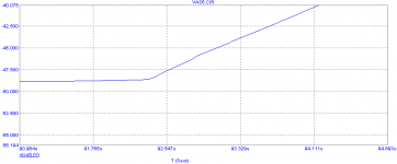
spike
Hi Arthur,
The quasi-saturation parameter QCO of the KSC3503 model is way too large: 0.05 Coulomb. I don't know what a realistic value would be, but below 1pC the spike is gone. The best way for determining QCO is a fit on a f T values under quasi-saturation conditions.
Cheers,
E.
Hello Pete,
The following are the models I use.
Regards
Arthur
Hi Arthur,
The quasi-saturation parameter QCO of the KSC3503 model is way too large: 0.05 Coulomb. I don't know what a realistic value would be, but below 1pC the spike is gone. The best way for determining QCO is a fit on a f T values under quasi-saturation conditions.
Cheers,
E.
numerous stuff
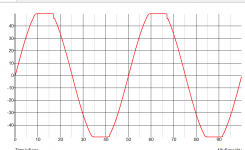
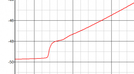
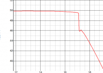
Hello Edmond,
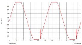
Attached is the waveform with models modified as you said. This may be a bit mental on my behalf but I have posted the tops and bottoms of the waveform to show a zoomed view of the recovery.
Do you have the same bumps in you waveform.
Pete,
The simulator I use is Simetrix.
Waly,
Thanks for the models much appreciated.
Bob,
Thanks for the link to you models.
Regards
Arthur
Hello Edmond,
Attached is the waveform with models modified as you said. This may be a bit mental on my behalf but I have posted the tops and bottoms of the waveform to show a zoomed view of the recovery.
Do you have the same bumps in you waveform.
Pete,
The simulator I use is Simetrix.
Waly,
Thanks for the models much appreciated.
Bob,
Thanks for the link to you models.
Regards
Arthur
Attachments
Last edited:
- Status
- Not open for further replies.
- Home
- Amplifiers
- Solid State
- Has anyone seen this front-end before?