Yup, i've made around from what i have on hand, not very well organized, but seems to be a monster amp, lots of power, i've made the first hi-power check with 3 18" B&C speakers rated at 1400w 8ohm each and almost blow'em up, but what remains silly is the distortion at low volume, so i asked workhorse already what to check in order to avoid such issue....Hi Kimberlator
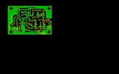
greetings pure coincindence only yesterday i designed pcb for this project
are you following schematic from post 36 thanks for replying
warm regards
andrew lebon
Cheers Andrew....😀
Hi Kimberlator
greetings thanks thanks at least now i know it works very kind of you
to keep us informed
warm regards
andrew lebon
greetings thanks thanks at least now i know it works very kind of you
to keep us informed
warm regards
andrew lebon
You can be sure that this design wont disappoint you, i'm certainly positive that i'm missing something and is causing this low-volume issue, but it is a beast, either if used for low freq coupled with lpf as well as with full range, sounds very well, here you can actually feel the power of this amp.Hi Kimberlator
greetings thanks thanks at least now i know it works very kind of you
to keep us informed
warm regards
andrew lebon
Whenever i have the time i'll post some pics of the last stage and monstruous psu i've built for this amp.
Have a great day Andrew, thanks for the quick reply...
Paul.🙂
yes WORKHORSE DESIGNS ROCK was thinking of this monster for a long time its for fun
hes in THE LEAGUE OF EXTRAORDINARY GENTLEMEN
ill finish it soon
warm regards
andrew lebon
hes in THE LEAGUE OF EXTRAORDINARY GENTLEMEN
ill finish it soon
warm regards
andrew lebon
You're right about that, seems like someone from outer-space give to him such knowledge, very electronics-skilled guy, the best part around this is the fact that he shares his brain-database with us and on top of that he helps everybody in anyway he can, no matter the level of difficult or nature of the issue to discuss, he always has the correct answer, great asset to DIY community, as well as other very skilled members of course, wish you the best luck on your project Andrew, Best Regards, Paul
I have a bunch of diy amp & pre-amp schematics that i've found on the net, just in case you need something alike, i can post here to open discuss, let me know.
Take care man...
Paul.
Take care man...
Paul.
![DSCN3308 [Desktop Resolution].JPG](/community/data/attachments/257/257323-e3736923be8148132a3a148bba5d2993.jpg?hash=43NpI76BSB)
Design of a CMOS LNA
Hello,
please i need to design a CMOS LNA. can any1 help me out with the circutry.i'll be using multism.
Thanks
Hello,
please i need to design a CMOS LNA. can any1 help me out with the circutry.i'll be using multism.
Thanks
Hello Andrew, clean nice job you have there!😀😀😀
Hi Kimberlator
greetings please can you tell which schematic you made this is the one with 560 ohms and 38k in input section this pcb is for trial run only
so only one pair mje15032 33
warm regards
andrew
Well, i've made the High-Power Version, the one with 12 TO-3 MJ21194 devices per rail, and, as stated before, i've made it salvaging other amps, just to verify if it's actually work or not, since seems to be some temp issues with the design, as well as some resistor values that need to be changed in order to get it work, please note that you certainly will need to stick pre-drivers on a heat sink, as well as the ones on the VAS, they actually reach unsafe temps if not attached to a heat sink, and remember that the "Diode-Connected" transistors to be placed on main heat sink, as they are the "Heat Tracking Devices".
Good luck Andrew,
Paul

Last edited:
Thats very old design of mine.
As Paul already said, the diode connected trannies must be attached to heatsink in order to get proper heat tracking. To enhance the low level signal clarity, put one more diode connected transistor in series with other two already in the schematic and set the trimmer accordingly to get 20mA idle current in output devices.
As Paul already said, the diode connected trannies must be attached to heatsink in order to get proper heat tracking. To enhance the low level signal clarity, put one more diode connected transistor in series with other two already in the schematic and set the trimmer accordingly to get 20mA idle current in output devices.
😀😀😀
Hi Kimberlator
greetings please can you tell which schematic you made this is the one with 560 ohms and 38k in input section this pcb is for trial run only
so only one pair mje15032 33
warm regards
andrew
Hello.,andrewlebon
May i have to see the PCB of your design.
I would like to make this Amp.
Thanks.
Jansaen
"Old Bullet-Proof Design"
Thank you Kanwar, sonics are very good indeed, one of the main interesting things about your design is the fact that looks like is a "Bullet-Proof" design, i've managed down to 1 - 1.5ohm without issues, other than the lots of heat to get rid off of it, but since main outputs are mounted on a well-suited heatsink it's no big deal.Thank you and hope to see some of your newer designs as well with 3 main objectives:Class AB, Compact and of course, Powerful.Thats very old design of mine.
As Paul already said, the diode connected trannies must be attached to heatsink in order to get proper heat tracking. To enhance the low level signal clarity, put one more diode connected transistor in series with other two already in the schematic and set the trimmer accordingly to get 20mA idle current in output devices.
Wiring Vol At Pre-Amp Input
Your Volume Pot Isn't Properly Connected At Pre-Amp Input.
Here Are The Correct & Incorrect Modes,
Check Out Both Andrew.
Best Regards.
Your Volume Pot Isn't Properly Connected At Pre-Amp Input.
Here Are The Correct & Incorrect Modes,
Check Out Both Andrew.
Best Regards.
Attachments
Last edited:
sir workhorse where is the circuit diagram ..pag paguni kan sa met...
Scroll back some pages and you will see, how silly for some members who don't do their homework and want spoon feeding.😀
Funny But True !!!
"Spoon Feeding" lol....😀😀😀Scroll back some pages and you will see, how silly for some members who don't do their homework and want spoon feeding.😀
Paa ji Sat Shri Akal ,
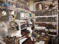
Is the circuit on page1 post6 of this thread complete. Kya yeh naachees can give this circuit a try with your guidance.Planning to pu 16 pairs 15024 - 25 that is toatl 32 in output. will a 2.5 kva transformer will be enough for this amp.Is nachhese ki choti si work shop ka photo saath hai.regards
Is the circuit on page1 post6 of this thread complete. Kya yeh naachees can give this circuit a try with your guidance.Planning to pu 16 pairs 15024 - 25 that is toatl 32 in output. will a 2.5 kva transformer will be enough for this amp.Is nachhese ki choti si work shop ka photo saath hai.regards
Attachments
- Status
- Not open for further replies.
- Home
- Amplifiers
- Solid State
- Has any one built this 1KW amp?