Hi Bob,
Sounds as if you're a man with a plan! Things are looking up. If you are into reading a bit, the 6L6GC is a beam power tube and the original tubes were true pentodes. A little searching over the weekend will explain the differences. Don't worry, the sky is not falling.
-Chris
Sounds as if you're a man with a plan! Things are looking up. If you are into reading a bit, the 6L6GC is a beam power tube and the original tubes were true pentodes. A little searching over the weekend will explain the differences. Don't worry, the sky is not falling.
-Chris
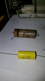
Chris, so the new coupling capacitors do not require any specific orientation (plus..... minus)? Bob
Hi Bob,
Correct. There used to be an indication as to which lead went to the outer foil. That would go to ground if it was a decoupling capacitor, or to the source of a signal if it was a coupling capacitor.
-Chris
Correct. There used to be an indication as to which lead went to the outer foil. That would go to ground if it was a decoupling capacitor, or to the source of a signal if it was a coupling capacitor.
-Chris
Finished rewiring the output sockets. They are mechanically done not soldered. Will perform final inspection and solder them. 6L6EH output tubes have been recieved.
After soldering will power up on the light bulb. If that test is okay planning on inserting full set of tubes and power up on light bulb. If that is okay try powering up on full power.
After soldering will power up on the light bulb. If that test is okay planning on inserting full set of tubes and power up on light bulb. If that is okay try powering up on full power.
Hi Bob,
The tube heater current may not allow the circuit to power up enough. Don't apply power without the output tubes and driver tubes. What you really need to use here is a variac. Variable AC transformer. With a variac, you control how much voltage to apply to the unit. So, you always know where you are at with no surprises. The load presented by a tube amp varies in steps. First the heater current job followed by some time with the B+ current draw. I honestly can't imagine doing this without using my variac.
-Chris
Chris, that's why I posted. I knew you were going to state this. Will remove BGW 750 from bench and get variac on the bench. It has a voltmeter but no current meter. Will use DVM as current meter and bring it up the way you suggest. Will post a schematic I may need some help on determing the heater current and B+ current.
Chris sent you via email a copy of the service manual. If you could give me further guidance on what currents to look for as this amp is powered up with the variac would be greatly appreciated.
Hi Bob,
It's not an exact thing. Just be aware that there are two events that draw current. I mentioned it so you wouldn't be taken by surprise.
I have never made a note as to how much current these amplifiers draw. I am more worried about fault current, not the absolute running current. I measure circuit conditions at a few points during power up. Those are about 30, 60 and 70 ~ 90 VAC input. I look at bias currents and DC offset. DC offset doesn't settle down until you are way up there. By 60 volts in, I am expecting bias current to start and DC offset to be within a couple volts to zero at the worst. No current draw is as bad as excessive current draw in my book. Offset stuck to a rail is uncommon by 30 volts in, but some amps will have large DC offset until half power or a little higher. Do check your zener regulated voltages a few times as you increase the voltages.
It's a feel thing. You'll get the hang of it, just don't look for absolutes. You are looking for gross failures.
-Chris
6L6GC tubes heater 6.3V at 0.9A. max
4×0.9A=3.6A max
12AX7 tube heater 6.3V at 0.3A max
5*0.3A=1.5A max
Total 5A maximum
fuse onboard is a 3A so one would anticipate seeing something much smaller than 3A when safely operating....less than 1 amp.
4×0.9A=3.6A max
12AX7 tube heater 6.3V at 0.3A max
5*0.3A=1.5A max
Total 5A maximum
fuse onboard is a 3A so one would anticipate seeing something much smaller than 3A when safely operating....less than 1 amp.
Last edited:
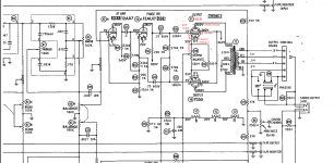
Marked up A500 schematic for 6L6 tube
so I correct my comment made in an earlier thread concerning the bias voltage being 35V that was the cathode voltage. The bias voltage is 5V. Now that I am getting close to being able to ruin the new 6L6 tubes thought I would try to understand how the tube works.
so I correct my comment made in an earlier thread concerning the bias voltage being 35V that was the cathode voltage. The bias voltage is 5V. Now that I am getting close to being able to ruin the new 6L6 tubes thought I would try to understand how the tube works.
Attachments
Hi Bob,
Still running today.
-Chris
Still running today.
Yup, less than 1 amp. Figure out the draw and turn that into watts. Multiply by about 1.1 then divide that by 120. That ought to give you your expected current draw at line level (Assuming the line is 120 VAC).fuse onboard is a 3A so one would anticipate seeing something much smaller than 3A when safely operating....less than 1 amp.
-Chris
Chris, just soldered up the rewired connections. I have the variac out and did a half *** set up but was hurrying. Stopped for the night need more time to set up correctly.
I get excited and start working too quickly, anything could happen need to slow down and think my way through. As stated set up the variac but too half assed a lot of alligator clips bare wires pushed into 115V sockets. No tubes installed brought it up to 20V pressed power button, nothing, brought it up to 50V pressed button nothing. Measured VAC at chassis it wasn't seeing the 50V, set up was to impromptu. So decided to take it apart and time permitting set it up correctly. The power pushbutton should be jumped, all tubes loaded, and properly set up the variac. I did put it back on the lightbulb and powered it up and it passes the test. So no hard shorts after psu capacitor change out and output socket rewire.
You should have stuck with the 7355
I don't want to rain on your parade but the fact of the matter is if you had just bought the 7355 you would have been playing music a week ago. While your current troubles may not be due to the socket rewiring for the 6l6 you still could not test your amp until the power tube sockets were sorted. Now, you have a problem that has been undiagnosed because attention was diverted elsewhere. But, I am sure with all the help that is available here you will be able to come out ok. Work carefully, and double and triple check your work. good luck! 808
I get excited and start working too quickly, anything could happen need to slow down and think my way through. As stated set up the variac but too half assed a lot of alligator clips bare wires pushed into 115V sockets. No tubes installed brought it up to 20V pressed power button, nothing, brought it up to 50V pressed button nothing. Measured VAC at chassis it wasn't seeing the 50V, set up was to impromptu. So decided to take it apart and time permitting set it up correctly. The power pushbutton should be jumped, all tubes loaded, and properly set up the variac. I did put it back on the lightbulb and powered it up and it passes the test. So no hard shorts after psu capacitor change out and output socket rewire.
I don't want to rain on your parade but the fact of the matter is if you had just bought the 7355 you would have been playing music a week ago. While your current troubles may not be due to the socket rewiring for the 6l6 you still could not test your amp until the power tube sockets were sorted. Now, you have a problem that has been undiagnosed because attention was diverted elsewhere. But, I am sure with all the help that is available here you will be able to come out ok. Work carefully, and double and triple check your work. good luck! 808
DAK808, At the moment I do not have any more problem/s than what I started with. I just need to take the time to properly set up the amp to perform initial power up using a variac. or maybe better said that I have no more problem than I had before the rewire of the sockets. This is an unrestored chassis received without tubes and has not been operated in more years than I would want to guess.
Next step is to properly set up the amp with a variac feeding it with an amp meter in the circuit. Installed the 4 used unknown state preamp tubes and used unknown state phase inverter tube this morning. Will install output tubes and perform initial power up using variac. Will post results.
Next step is to properly set up the amp with a variac feeding it with an amp meter in the circuit. Installed the 4 used unknown state preamp tubes and used unknown state phase inverter tube this morning. Will install output tubes and perform initial power up using variac. Will post results.
Last edited:
too many unknowns
It is hard to confidently troubleshoot when you have too many unknowns. Even your tubes have not been tested in a working amp. I hope it all works out for the best. My main point was that it is better to make changes from a known working amp so that you know or have a good idea where a problem could be if one crops up. cheers.
Installed the 4 used unknown state preamp tubes and used unknown state phase inverter tube this morning. Will install output tubes and perform initial power up using variac. Will post results.
It is hard to confidently troubleshoot when you have too many unknowns. Even your tubes have not been tested in a working amp. I hope it all works out for the best. My main point was that it is better to make changes from a known working amp so that you know or have a good idea where a problem could be if one crops up. cheers.
- Home
- Amplifiers
- Tubes / Valves
- Harmon Kardon A50K project