Good idea, a sub woofer. But for that you can even use a special transformer which is optimised for that.Regarding the high frequency rolloff of transformers such as the 1628SE . . .
Most likely cause: a Very high leakage reactance between the primary and secondary (poor high frequency coupling).
Next level factor: High distributed capacitance across the primary.
Lowest level factor: The absence of Litz wire.
At the other end of the spectra:
The 1628SE had the best low frequency rolloff of any single ended transformer I ever bench tested using the
$50,000 Rhode & Schwarz Vector Network Analyzer.
Driving the 5k primary with a 1k impedance, It was not yet rolled off by 1dB at 10Hz.
(or to say it this way: not yet rolled off by 3dB at 5 Hz). Sub 5 Hz response indeed!
If you have a pair, you might build subwoofer tube amplifiers out of them.
Just my $50,000 opinion
In post 36 you see a 3300 Ohm transformer with about 4,5Hz to 100kHz bandwidth. Can be easely lower if you wanted with a little bit loss at higher frequencies.
At least you can do something good with the Hammond 🙂 The Fiat is nowhere good
When you test a transformer, be sure to put a resistor in series with the winding you are driving.
Example 1:
With an 8 Ohm non-inductive load on the secondary 8 Ohm tap,
Drive a 5k primary with a 50 Ohm generator, and get sub 1 Hz bandwidth.
Drive the same 5k primary with a 1k series resistor, and get 10Hz, 20Hz, or 30Hz, etc. bandwidth. (like a plate impedance, rp, of 1k).
Example 2:
If you drive the secondary with a Sub-1 Ohm solid state power amplifier, you will get a very good low frequency bandwidth,
but it you will never get that same low frequency response when you build the complete amplifier.
Instead, on the 8 Ohm tap, start with (1000/5000) x 8 = 1.6 Ohm series resistor (assuming a solid state amplifier with a damping factor of 50 (8/50 = 0.16 Ohms, a 10% error, so use a 1.6 - 0.16 = 1.44 Ohm series resistor).
Be sure to load the secondary with a 5k Ohm resistor.
Look at it this way:
1k Ohm drives 5k primary; 8 Ohm loads the 8 Ohm tap.
Or, driving the transformer the other way:
0.144 Ohm drives the 8 Ohm tap, 5k loads the 5k primary.
(the setup that most emulates the situation in the real amplifier; assuming the plate rp is 1k Ohm and the 8 Ohm load is 8 Ohms in the amplifier).
Of course, for a single ended transformer, the actual low frequency response will change, according to the DC quiescent current in the primary and the particular transformer that is tested (things like quiescent DC Amp x Turns, the laminations, and the air gap).
Suppose you are going to test a 5k primary and 8 Ohm secondary, with quiescent DC of 50 mA on the 5k primary.
But, the turns ratio is 25:1; if instead you drive the secondary, you need 25 x 50mA = 1.25A DC quiescent secondary current.
A 50mA current source, or a 1.25A current source to do the testing, your choice.
Happy transformer testing!
When you test a transformer, be sure to put a resistor in series with the winding you are driving.
Example 1:
With an 8 Ohm non-inductive load on the secondary 8 Ohm tap,
Drive a 5k primary with a 50 Ohm generator, and get sub 1 Hz bandwidth.
Drive the same 5k primary with a 1k series resistor, and get 10Hz, 20Hz, or 30Hz, etc. bandwidth. (like a plate impedance, rp, of 1k).
Example 2:
If you drive the secondary with a Sub-1 Ohm solid state power amplifier, you will get a very good low frequency bandwidth,
but it you will never get that same low frequency response when you build the complete amplifier.
Instead, on the 8 Ohm tap, start with (1000/5000) x 8 = 1.6 Ohm series resistor (assuming a solid state amplifier with a damping factor of 50 (8/50 = 0.16 Ohms, a 10% error, so use a 1.6 - 0.16 = 1.44 Ohm series resistor).
Be sure to load the secondary with a 5k Ohm resistor.
Look at it this way:
1k Ohm drives 5k primary; 8 Ohm loads the 8 Ohm tap.
Or, driving the transformer the other way:
0.144 Ohm drives the 8 Ohm tap, 5k loads the 5k primary.
(the setup that most emulates the situation in the real amplifier; assuming the plate rp is 1k Ohm and the 8 Ohm load is 8 Ohms in the amplifier).
Of course, for a single ended transformer, the actual low frequency response will change, according to the DC quiescent current in the primary and the particular transformer that is tested (things like quiescent DC Amp x Turns, the laminations, and the air gap).
Suppose you are going to test a 5k primary and 8 Ohm secondary, with quiescent DC of 50 mA on the 5k primary.
But, the turns ratio is 25:1; if instead you drive the secondary, you need 25 x 50mA = 1.25A DC quiescent secondary current.
A 50mA current source, or a 1.25A current source to do the testing, your choice.
Happy transformer testing!
Hi
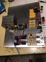
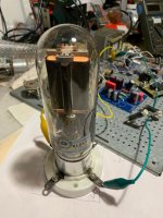
in attach the test set to drive dc current on secondary of a s.e. OT ; it is a proto working. It is missing a external DC poer supply to put current on secondary as current generator. There is a power amplifier that can deliveri aroud 25 Vrms on 8 ohms with a good perfromances, it drives the secondary with ptoper signal.
Done two years ago just only to check the validity of the reverse test. Done few test, I am taking long time to do the things!
Attachments
For a good external bias supply ccs are very usefull, specially for low frequencies. For high frequencies you need a cascoded ccs.
Instead to write a lot of words why you don't show someting better than two screenshot of a trafo with a swing of +/- 80 mV?
And if you are sure that the reverse method is not so good, why you dn't show a real report to explain the issues of the method?
Very simple.
If you are interested, of course otherwise are only words.
Then in post 39 there are the test for three OT with same circuit; as you see the FIAT trafo is the better compared the others.
And I have paid to get the Hammond and Sowter just to have a standard reference to compare with the proto.
About post 39, please show us the real circuit you mentioned and how is working; otherwise are only words.
The solution I have adopted is simply end efficent and built in a proto. The only thing is the proper setting of the resistors.
Walter, you are a stiff-headed person who does not understand how a transformer works.
This +- 80mV is perfect in the normal audio range, in dB in the middle.
Read this link again https://www.diyaudio.com/community/threads/opt-characterization.313957/page-3
Post 22, 30, 35, 44, 46 and many more.
It doesn't matter how many measurements I or others do because you deny everything because you only believe in your own words.
I also still can't follow you why you give a bunch of mediocre transformers so much attention. Or do you really think the Fiat transformer was good? Far from it.
I test a lot of Output transformers and Interstage transformers at low power levels. DCR, frequency response, impedance, square wave response, etc. That is just the start.
But nothing works better to show the good (or shows the worse) than when they are tested in the best test fixture in the world . . .
a working amplifier.
When doing complete testing of the transformers, I do not use negative feedback to test the transformers, that would mask the total distortion frequency response, and square wave response of the total driver tube and Interstage, or the total output tube(s) and output transformer.
The exceptions would be the local negative feedback of either:
Ultra Linear if employed,
Or, Triode wiring of Pentode / Beam Power tubes if they are employed that way.
You have to know something about the distortion and frequency response of the tube circuit (Miller Capacitance; coupling capacitors; bypass capacitors; plate impedance, rp; etc.) so that you can estimate the distortion and frequency response due to the output transformer and Interstage transformer.
And do not forget to test the square wave response in the actual amplifier too.
Some forget that a push pull Interstage or push pull Output transformer need to be tested with DC bias (the same bias that is equal to the driver tube DC current un-balance, and output tube current un-balance. Do this with the 'Live' amplifier (you do measure the DC un-balanced current of your driver tubes and output tubes, don't you?). If not, you should.
Only after those tests can you apply negative feedback if you wish, and do some more 'Live' testing.
Just my practice, and just my opinions.
Nice work.I test a lot of Output transformers and Interstage transformers at low power levels. DCR, frequency response, impedance, square wave response, etc. That is just the start.
But nothing works better to show the good (or shows the worse) than when they are tested in the best test fixture in the world . . .
a working amplifier.
When doing complete testing of the transformers, I do not use negative feedback to test the transformers, that would mask the total distortion frequency response, and square wave response of the total driver tube and Interstage, or the total output tube(s) and output transformer.
The exceptions would be the local negative feedback of either:
Ultra Linear if employed,
Or, Triode wiring of Pentode / Beam Power tubes if they are employed that way.
You have to know something about the distortion and frequency response of the tube circuit (Miller Capacitance; coupling capacitors; bypass capacitors; plate impedance, rp; etc.) so that you can estimate the distortion and frequency response due to the output transformer and Interstage transformer.
And do not forget to test the square wave response in the actual amplifier too.
Some forget that a push pull Interstage or push pull Output transformer need to be tested with DC bias (the same bias that is equal to the driver tube DC current un-balance, and output tube current un-balance. Do this with the 'Live' amplifier (you do measure the DC un-balanced current of your driver tubes and output tubes, don't you?). If not, you should.
Only after those tests can you apply negative feedback if you wish, and do some more 'Live' testing.
Just my practice, and just my opinions.
Last edited:
I test a lot of Output transformers and Interstage transformers at low power levels. DCR, frequency response, impedance, square wave response, etc. That is just the start.
But nothing works better to show the good (or shows the worse) than when they are tested in the best test fixture in the world . . .
a working amplifier.
When doing complete testing of the transformers, I do not use negative feedback to test the transformers, that would mask the total distortion frequency response, and square wave response of the total driver tube and Interstage, or the total output tube(s) and output transformer.
The exceptions would be the local negative feedback of either:
Ultra Linear if employed,
Or, Triode wiring of Pentode / Beam Power tubes if they are employed that way.
You have to know something about the distortion and frequency response of the tube circuit (Miller Capacitance; coupling capacitors; bypass capacitors; plate impedance, rp; etc.) so that you can estimate the distortion and frequency response due to the output transformer and Interstage transformer.
And do not forget to test the square wave response in the actual amplifier too.
Some forget that a push pull Interstage or push pull Output transformer need to be tested with DC bias (the same bias that is equal to the driver tube DC current un-balance, and output tube current un-balance. Do this with the 'Live' amplifier (you do measure the DC un-balanced current of your driver tubes and output tubes, don't you?). If not, you should.
Only after those tests can you apply negative feedback if you wish, and do some more 'Live' testing.
Just my practice, and just my opinions.
Hi
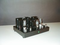
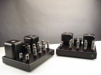
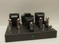
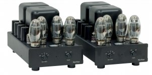
in attach some photo of the amps I made ( not all) with a good aesthetic.
I put htis photo to specify that each of them has a OT trafo non commercial and buil from two company ( one, the old brand Ripley, is missing, I can't find the photo) and all are tested at the best, in my opinion.
The installation on amps are done after some tests; then verified the functions on test set ( I have two Audio Precision, 5 tube tester, included Sofia, then generator, etc, etc)
Forgot, around 10.000 pcs of Resista WK series and around 4.000 pcs of Holco resistor (H2,H4,H8) plus hundreds of capacitors. And a non verified number of tubes.
I sent the protos to a good number of friend and ex customer to test the music results. I have this fortune to know a lot of people who have HiFi setup from 1.000 euros to dozen of euros. Then if the feedback is common ( I mean as pleasure in listening sessions) this give an idea that the project is good.
This is the last act to close the project.
There are amps that are running from year 2000 ( few last years of century) with a very low number of fails ( of course mainly tubes) wtih a happy listener.
Bye for the moment 🙂
Ps= it seems to be off-topic but maybe this discussion can help
Attachments


Last edited:
Ahhh, so you are a manufacturer? Why didn't you say that in the first place?Hi
in attach some photo of the amps I made ( not all) with a good aesthetic.
I put htis photo to specify that each of them has a OT trafo non commercial and buil from two company ( one, the old brand Ripley, is missing, I can't find the photo) and all are tested at the best, in my opinion.
The installation on amps are done after some tests; then verified the functions on test set ( I have two Audio Precision, 5 tube tester, included Sofia, then generator, etc, etc)
Forgot, around 10.000 pcs of Resista WK series and around 4.000 pcs of Holco resistor (H2,H4,H8) plus hundreds of capacitors. And a non verified number of tubes.
I sent the protos to a good number of friend and ex customer to test the music results. I have this fortune to know a lot of people who have HiFi setup from 1.000 euros to dozen of euros. Then if the feedback is common ( I mean as pleasure in listening sessions) this give an idea that the project is good.
This is the last act to close the project.
There are amps that are running from year 2000 ( few last years of century) with a very low number of fails ( of course mainly tubes) wtih a happy listener.
Bye for the moment 🙂
Ps= it seems to be off-topic but maybe this discussion can help
I was a manufacterer.
Those amps are from the past.
I have a little collaboration with a shop in Italy but not for amplifier mainly for phono stuff
Now I have a lab for my pleasure, first of all.
And I am writing, sometimes, some article on Audioreview magazine in Italy.
And in every case aren't on market.
Please let me know your stuff, also only for your interest; I suppose you have some beautiful project to watch.
Forgot, around 10.000 pcs of Resista WK series and around 4.000 pcs of Holco resistor (H2,H4,H8) plus hundreds of capacitors. And a non verified number of tubes.I was a manufacterer.
Those amps are from the past.
I have a little collaboration with a shop in Italy but not for amplifier mainly for phono stuff
Now I have a lab for my pleasure, first of all.
And I am writing, sometimes, some article on Audioreview magazine in Italy.
And in every case aren't on market.
Please let me know your stuff, also only for your interest; I suppose you have some beautiful project to watch.
You want to sell those? Which tubes you have? You have MKV capaciters?
I don't sell anything.
I will play on my own circuit and make tests; not words.
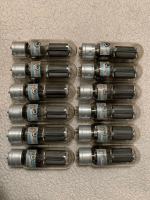
Ps= I have 10 pcs of 845 Fivre (RCA) year 1942, new and tested, if you want them they cost 1.000 euros each.
In photo are 12 but two are sold
Try to use them with your OT. WIll be a amazing amp
Bye
Walter
I will play on my own circuit and make tests; not words.
Ps= I have 10 pcs of 845 Fivre (RCA) year 1942, new and tested, if you want them they cost 1.000 euros each.
In photo are 12 but two are sold
Try to use them with your OT. WIll be a amazing amp
Bye
Walter
Attachments
Sorry, not an interesting tube any more, i have better at home for far less.I don't sell anything.
I will play on my own circuit and make tests; not words.
Ps= I have 10 pcs of 845 Fivre (RCA) year 1942, new and tested, if you want them they cost 1.000 euros each.
In photo are 12 but two are sold
Try to use them with your OT. WIll be a amazing amp
Bye
Walter
- Home
- Amplifiers
- Tubes / Valves
- Hammond and Edcor SE X'fmrs compared