Hi
I can't understand wich are the voltages you are using in these test.
On the second plot I read +/- 80 mV, it is right?
Walter
I can't understand wich are the voltages you are using in these test.
On the second plot I read +/- 80 mV, it is right?
Walter
tubes4all,
Very interesting.
What is the cause of the pre-transition spike?
Usually, only digital signal sources have pre-ringing.
It might be nice to zoom into that detail.
Very interesting.
What is the cause of the pre-transition spike?
Usually, only digital signal sources have pre-ringing.
It might be nice to zoom into that detail.
Maybe my digitalscoop and tonegenerator?tubes4all,
Very interesting.
What is the cause of the pre-transition spike?
Usually, only digital signal sources have pre-ringing.
It might be nice to zoom into that detail.
The signal of +/- 80 mV of square wave is not esplicative of the trafo.
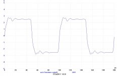
In attach the test on 10 Khz with Litz trafo and a swing of +/-3 volt (around) on scale exactly 40 times your test.
The results is not so bad but we can do it better.
The secondd is the standard trafo at 10 kHz at +/- 4V p-p
In my opinion these type of tests are esplicative
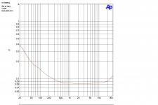
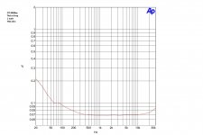
Then two test on THd vs Freq, another intersting test ; 1 watt as power test
The first one is with the primary ( on my set uo now secondary) at 2500 ohm load, as following the tech. spec of the rafo; I think a fgood results, the iron can be better.
The second is with a load of 750 ohm close to the real Rp of one 300B; same setuo. Also a good results.
Both is done with a standard trafo ( proto)
In attach the test on 10 Khz with Litz trafo and a swing of +/-3 volt (around) on scale exactly 40 times your test.
The results is not so bad but we can do it better.
The secondd is the standard trafo at 10 kHz at +/- 4V p-p
In my opinion these type of tests are esplicative
Then two test on THd vs Freq, another intersting test ; 1 watt as power test
The first one is with the primary ( on my set uo now secondary) at 2500 ohm load, as following the tech. spec of the rafo; I think a fgood results, the iron can be better.
The second is with a load of 750 ohm close to the real Rp of one 300B; same setuo. Also a good results.
Both is done with a standard trafo ( proto)
Attachments

I did another test: limited frequency respons from my tonegenerator. Now it is max 200kHz (instead of 20MHz)Maybe my digitalscoop and tonegenerator?
1kHz squarewave
This is at 10kHz.
As you can see is that filtering dos a great job. The Audioprecision system for instance is also a limited system (200kHz) so you don't see all the high frequncy **** what could be in your transformer signal. Luckely most people use gridstoppers and amplifier stages with a natural limit (Miller capacity mostly).
btw: a larger signal dos not make the measurements better or worse.
Last edited:
The main problem, in my opinion, is not to see what happen at more than 200 kHz.
The main problem is what appen from 10 Hz to 30 kHz ( p.e.) with mainly THD vs frequency.
At different level. Not only a low level
In this range, looking to the curve, you can see what the OT only is capable to do.
I mean with the reverse OT test configuration.
The square tell you something of course.
I agree, the 10Hz -30kHz is what we like to have flawless. It helps when we have resonances way out of the audioband >300kHz or more.
This helps because of less filtering in the normal audioband. I not like to add a filter because my transformer isn't good enough.
And i also pay a lot of money for the transormer so please let is be as good as possible.
Secondly if there is feedback a clean bandwidth helps a lot for the feedback stability. Most feedback sucks because of all those ringing problems.
People say that they don't like fb, yes, because there transformer isn't good to apply fb and good fb is difficult .
Your reverse OT test is another way to test a transformer, NOT a better test and because many transistor amps are not so good above 20kHz probably a worse test for frequency measurements (and squarewaves)
For me a lower sinal test is far more interesting because the details of the audio signal are not at high output but at low signal output. I don't have the time to do those measurements all the time, once in a while i do but mainly i like a better design from the start ( so none of the transformers you measured i would buy onless the price is below 50 euro and it would be for a guitar amp)
Last edited:
On the whole the high frequency response of an OPT is less important that the LF, mid response & inherent stabilty, at least to my ears anyway. That's where most of music content sits frequency wise and our ears roll off naturally towards the top end whatever our age. Also when it comes down to it we listen to music not test gear, just my experience and extensively testing a few self designed and built amps.
Matt,Primary Windings in the UK might be worth a punt, I used two of their OPT's in a PP AB2 amp build and am well chuffed. There was a bit of a wait though - https://primarywindings.com/single-ended-output-transformers/
Andy.
Matt,Primary Windings in the UK might be worth a punt, I used two of their OPT's in a PP AB2 amp build and am well chuffed. There was a bit of a wait though - https://primarywindings.com/single-ended-output-transformers/
Andy.
On the whole the high frequency response of an OPT is less important that the LF, mid response & inherent stabilty, at least to my ears anyway. That's where most of music content sits frequency wise and our ears roll off naturally towards the top end whatever our age. Also when it comes down to it we listen to music not test gear, just my experience and extensively testing a few self designed and built amps.
Matt,Primary Windings in the UK might be worth a punt, I used two of their OPT's in a PP AB2 amp build and am well chuffed. There was a bit of a wait though - https://primarywindings.com/single-ended-output-transformers/
Andy.
That's mostly okay if you don't use feedback, and you're satisfied with the resulting bandwidth, but if you want or need to use global feedback in the design, transformer response at the frequency extremes can be critical in creating a stable amplifier.
Probably I was not able to explain my point of view
But is not possible to discuss a performance of one trafo with mV!
And with two simply test.
With a square wave of +/- 80 mV we can understand everything?
It is a joke?
Everyone who start to build a ampifier with tube want to have the best results from 0,001 w to maximum, or not?
Again, the use of a ss amps for reverse test can be mandatory and it is easy to find a cheaper high power amp from ALiexpress, clone from some venerable brand; it you buy a 200 watt fet amps, can delivery 40 volt on 8 ohm, you can use 10 volts (1/4) to have a resonable swing at very low thd ( with a 1:20 ratio you have 180 Vrms as test signal)
And , in every case, you can subtract ( with the THD vs freq) the residual of ss amp from final results.
At Audioreview we are testing all amps from the low level at the high to show the potential or, in case, the issues. And in most cases we explain the circuit and write a comments about it.
If someone don't want to buy a trafo with the test result I posted is also true thet is not possible to buy a trafo with only two test with mV as amplitude.
Walter
Last edited:
I think you are over reacting Walter.Probably I was not able to explain my point of view
But is not possible to discuss a performance of one trafo with mV!
And with two simply test.
With a square wave of +/- 80 mV we can understand everything?
It is a joke?
Everyone who start to build a ampifier with tube want to have the best results from 0,001 w to maximum, or not?
Again, the use of a ss amps for reverse test can be mandatory and it is easy to find a cheaper high power amp from ALiexpress, clone from some venerable brand; it you buy a 200 watt fet amps, can delivery 40 volt on 8 ohm, you can use 10 volts (1/4) to have a resonable swing at very low thd ( with a 1:20 ratio you have 180 Vrms as test signal)
And , in every case, you can subtract ( with the THD vs freq) the residual of ss amp from final results.
At Audioreview we are testing all amps from the low level at the high to show the potential or, in case, the issues. And in most cases we explain the circuit and write a comments about it.
If someone don't want to buy a trafo with the test result I posted is also true thet is not possible to buy a trafo with only two test with mV as amplitude.
Walter
I did not say that we know everything with a single squarewave. These are your words.
It dosn’t mater if you use a small sq signal or a larger signal (3V) because the transformer handles both signals equally so if i use a larger signal the outcome will be exactly the same.
what we know is that thd will be higher with larger signal and higher at low frequencies. So a better low frequency response is a good thing. For high frequencies about the same but the mechanism why is different.
It has a lot to do with the core and the windings. Litz wire however is not needed and has normally no bennifits (no skin effect problems for normal wires)
Last edited:
Walter, I have already tested the transformer in the past with a tube with much larger signals and to reassure you, my measurements are correct, also those with +- 80mV (output secondary). The results, as the theory indicates, are the same. Those low outputs are not that special in dB terms. I also don't understand why you make such a fuss about that.
Btw i have a lot of Litz wire (for transformers) so maybe i wil make a special version in the future. That wil not be with a standerd iron core, not even the 0,05mm cores i have . I will use better cores for that.
Btw i have a lot of Litz wire (for transformers) so maybe i wil make a special version in the future. That wil not be with a standerd iron core, not even the 0,05mm cores i have . I will use better cores for that.
Last edited:
At the time this Hammond trafo was know to have bad treble performance on the audiophile community what are who use the product, so to try fix it Hammond released the SEA version.Hi
The test from SAC are not specified in the details so the results can't be take in consideration.
And the method is wrong because it takes the entire ouput stage and not the trafo itself.
So the parasitic of the tube interact with the parasitic of the trafo
Plus other considerations
Walter
Measure an component on the circuit is the right way to do a useful test the component will be used on the circuit not on a bench test.
To Tubes.
I am not agree. The OT is not a linear device so if you can undestand what it is capable to do you have to test at different level with swings in frequency.
That's all.
And the reverse method is the simplest and efficent way.
The use of Litz is just ot understand the differences with a standard wire; probably aren't so big but at high frequency a difference is noted.
To Full range
In my opinion the test with an OT outside the circuit is th only way to have clearly what it can do.
Mainly at low frequency ( L + nucleus) and at high frquencies ( quality of coils winding and capacitive parasitic)
With the power stage there is an interaction with tubes.
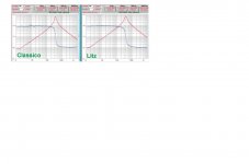
In attach a screenshot of a test on three OT done from my collegue Fabrizio.
It is possible to see the shape of a impedance of primary winding ( secondary open) .
Until the resonance the module curve is inductive, after that it is capacitive
The numbers on screenshot aren't not so clear to read.
These are my pint of view
I am not agree. The OT is not a linear device so if you can undestand what it is capable to do you have to test at different level with swings in frequency.
That's all.
And the reverse method is the simplest and efficent way.
The use of Litz is just ot understand the differences with a standard wire; probably aren't so big but at high frequency a difference is noted.
To Full range
In my opinion the test with an OT outside the circuit is th only way to have clearly what it can do.
Mainly at low frequency ( L + nucleus) and at high frquencies ( quality of coils winding and capacitive parasitic)
With the power stage there is an interaction with tubes.
In attach a screenshot of a test on three OT done from my collegue Fabrizio.
It is possible to see the shape of a impedance of primary winding ( secondary open) .
Until the resonance the module curve is inductive, after that it is capacitive
The numbers on screenshot aren't not so clear to read.
These are my pint of view
I think your point of view is not so correct.
Yes, compared to a resistor its less linear, compared to a transistor more linear. At the excitation levels you and i use it it is very linear, even your own measurements show that. The most problems will be at the end of the BH-loop. But a 2500Ω tansformer and 300B tube als have other problems because probably the tube will run out of current because the load line is anyway to steep.
Somewhere at this forum another guy (Timpert?) showed you that your method is not very good, it is an easy method but not very accurately. To know how low the distortion in a transformer can be your secondary serie resistor even defines the level of distortion and not the transformer because the resistor will limit the current what is needed for low distortion. That same guy earlier showed you that too. So the set-up has (strong) limitations.
btw, the litzwire version has more resonances, why? If it was made exactly the same it should have the same high frequency response because the differences in wire is not big enough and the cores are the same.
I confirm you that the reverse test system is the best way to understand the OT itself, no other way are available until you find a generator with variable Zout and a wide range of Vout at different frequencies.
In the thread you mentioned I put two diagrams with a standard mode and reverse mode and the curve are similar. The amplitude was different of course.
But the THD vs frequency, as shown in other diagrams are different related to the level, mainly on low end and high end.
That's all.
Your considerations around the OT and the resistor put in series are wrong . If you are sure about it you can show with test your point of view, I suppose.
Regarding the Litz version the resonance frequency is a bit higher than normal ( as expected) and you can read that a high frequency the value of capacitance is 100 pF less respect to the normal and the frequency answer is better.
Attachments
No Walter, it is only you who says that is the best test, others disagree.I confirm you that the reverse test system is the best way to understand the OT itself, no other way are available until you find a generator with variable Zout and a wide range of Vout at different frequencies.
In the thread you mentioned I put two diagrams with a standard mode and reverse mode and the curve are similar. The amplitude was different of course.
But the THD vs frequency, as shown in other diagrams are different related to the level, mainly on low end and high end.
That's all.
Your considerations around the OT and the resistor put in series are wrong . If you are sure about it you can show with test your point of view, I suppose.
Regarding the Litz version the resonance frequency is a bit higher than normal ( as expected) and you can read that a high frequency the value of capacitance is 100 pF less respect to the normal and the frequency answer is better.
It is not a problem to make a generator with high output voltages and low distortion. Ever heard of tube circuits? Srpp, Mu stage, Mu followers? They don't have 0.0000001% distortion and the output voltages are not 400Vrms either, but they are capable of excellent work,. You can even combine tube circuits with gyrators, ccs, fets and other things to make it even better.
In that thread I didn't mean your measurements but Timpert's measurement (I think he was the guy who did it) .
If you understand the physics behind transformers then you know that you need a device that can deliver enough current to keep the distortion low. The moment you put a series resistor in the circuit things go wrong. But I'm afraid you missed the brieving ....(or don't understand that a resistor limits the current).
I won't do any measurements to prove that because it's just transformer theory, you either understand the theory or you don't.
"As for the Litz version, the resonant frequency is slightly higher than normal (as expected)" Ohhh, you found a new theory?
Why is the capacitance 100pF less, is that the winding capacitance or the capacitance between primary and secondary? So they are not wound the same way.
In addition, resonances are the result of poor/limited winding technique.
Regarding the high frequency rolloff of transformers such as the 1628SE . . .
Most likely cause: a Very high leakage reactance between the primary and secondary (poor high frequency coupling).
Next level factor: High distributed capacitance across the primary.
Lowest level factor: The absence of Litz wire.
At the other end of the spectra:
The 1628SE had the best low frequency rolloff of any single ended transformer I ever bench tested using the
$50,000 Rhode & Schwarz Vector Network Analyzer.
Driving the 5k primary with a 1k impedance, It was not yet rolled off by 1dB at 10Hz.
(or to say it this way: not yet rolled off by 3dB at 5 Hz). Sub 5 Hz response indeed!
If you have a pair, you might build subwoofer tube amplifiers out of them.
Just my $50,000 opinion
Last edited:

I see also 25% differance in induction.I confirm you that the reverse test system is the best way to understand the OT itself, no other way are available until you find a generator with variable Zout and a wide range of Vout at different frequencies.
In the thread you mentioned I put two diagrams with a standard mode and reverse mode and the curve are similar. The amplitude was different of course.
But the THD vs frequency, as shown in other diagrams are different related to the level, mainly on low end and high end.
That's all.
Your considerations around the OT and the resistor put in series are wrong . If you are sure about it you can show with test your point of view, I suppose.
Regarding the Litz version the resonance frequency is a bit higher than normal ( as expected) and you can read that a high frequency the value of capacitance is 100 pF less respect to the normal and the frequency answer is better.
- Home
- Amplifiers
- Tubes / Valves
- Hammond and Edcor SE X'fmrs compared